NiftyKeyz mod: smaller jack board
All along the plan for my rack was 4-voice polyphony. I intended to make a MIDI-to-CV module with different modes for split voicings and even wrote some of the logic for it. But ultimately the high-resolution DACs ended up being two expensive and unwieldy. Instead I got a Cre8audio NiftyKeyz modular keyboard. While a bit pricey, it had the split functions I wanted and a bunch of other features I wouldn’t have had, including a powerful arpeggiator, mod wheels, a latch function, etc.
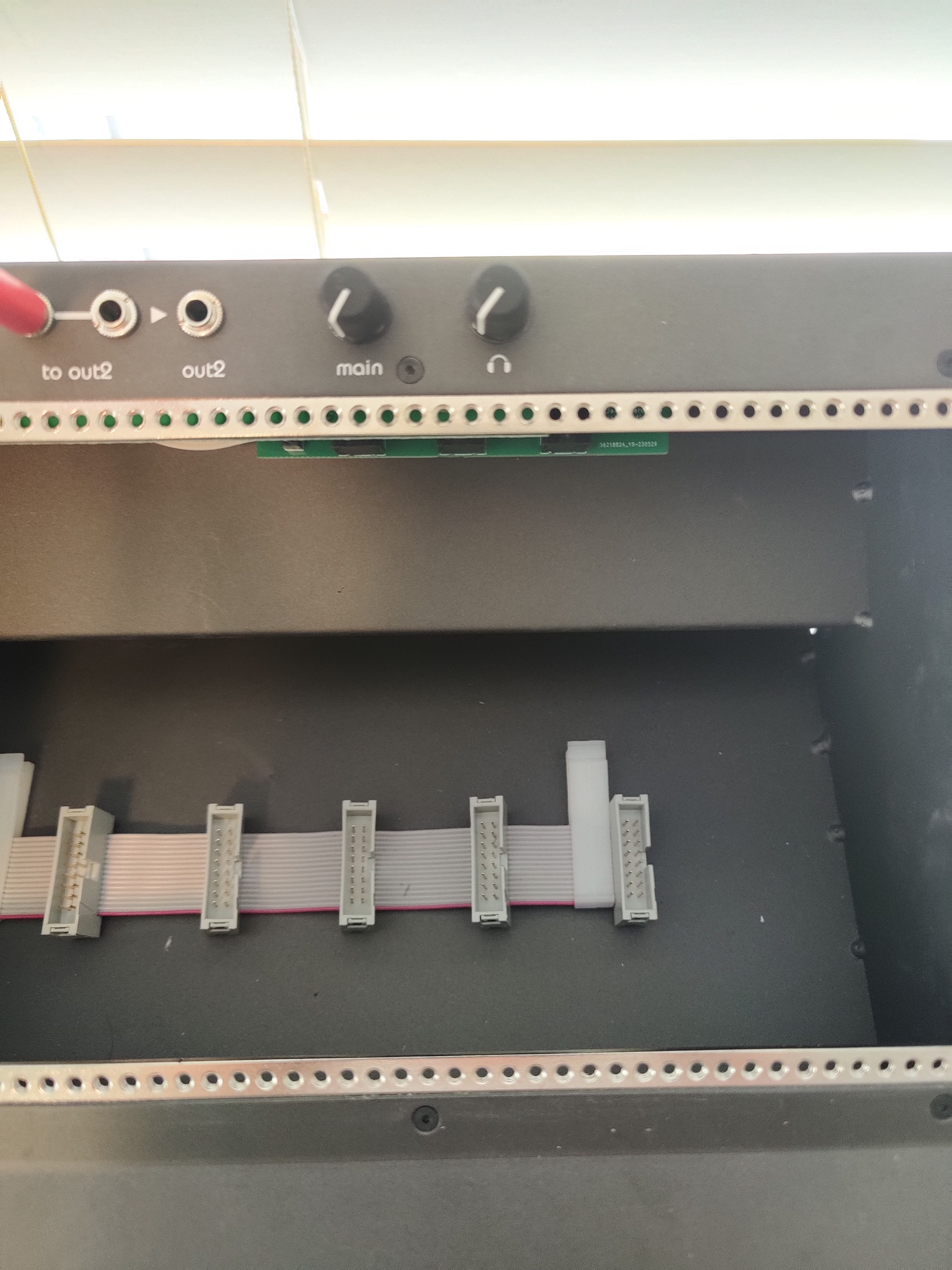
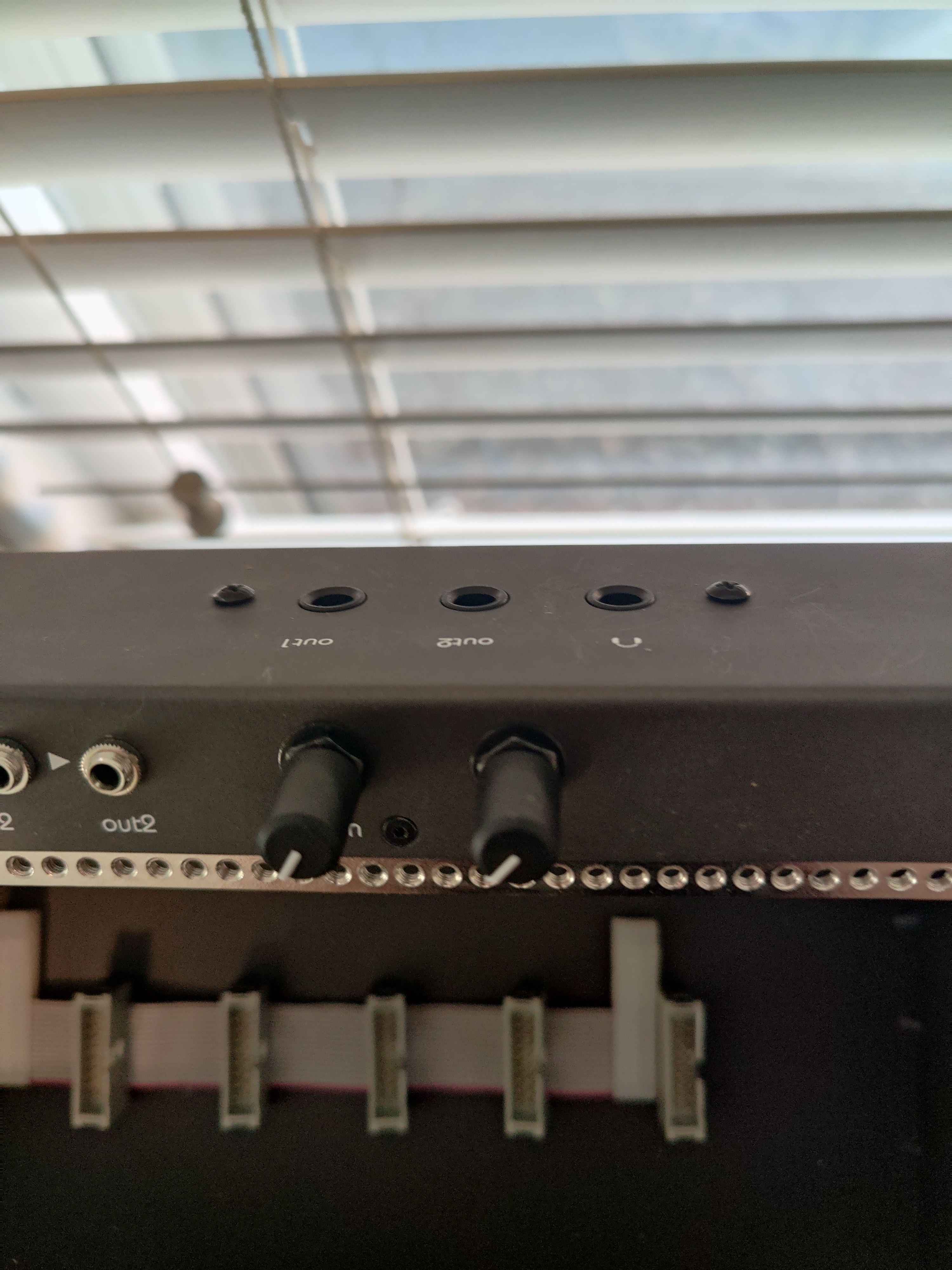
While I do really like it, there are a few design decisions that I find irksome. One is the fact that the PCB that mounts the 1/4” output jacks to the case is too tall, protruding about 8.5 mm into the rack space where the modules should go. This causes deep modules on the right side of the rack to not quite fit properly.
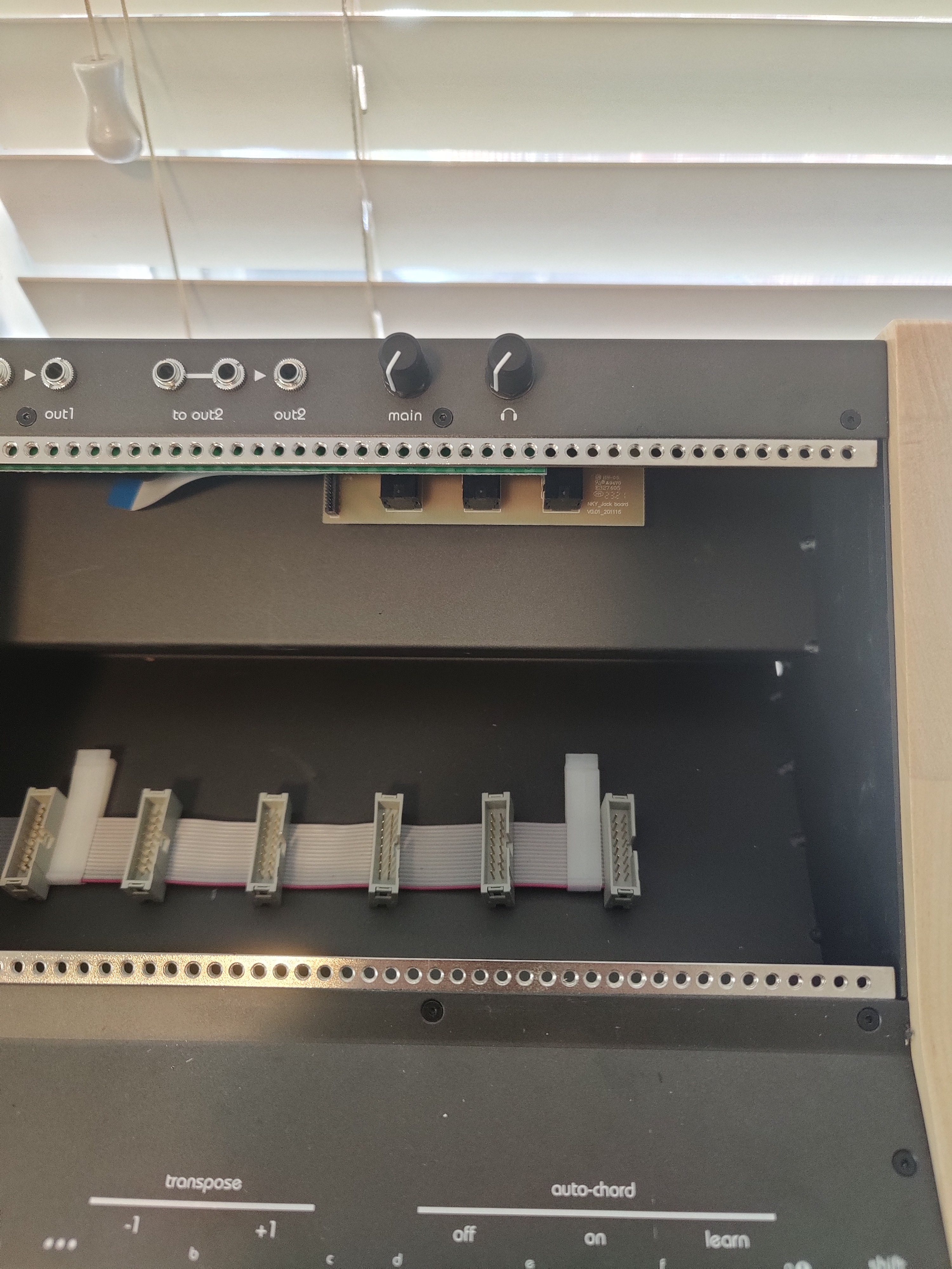
I thought perhaps I could shave down the PCB to fit, but looking at it, all the traces are in those 8mm. Why it’s like that I don’t know, but my guess is they wanted to do a single-layer board but doing without vias only works if the traces are below the jacks, otherwise there’s a knot. Rather than spring for the extra few cents for a two-layer board, they decided to just cut into the rack space.
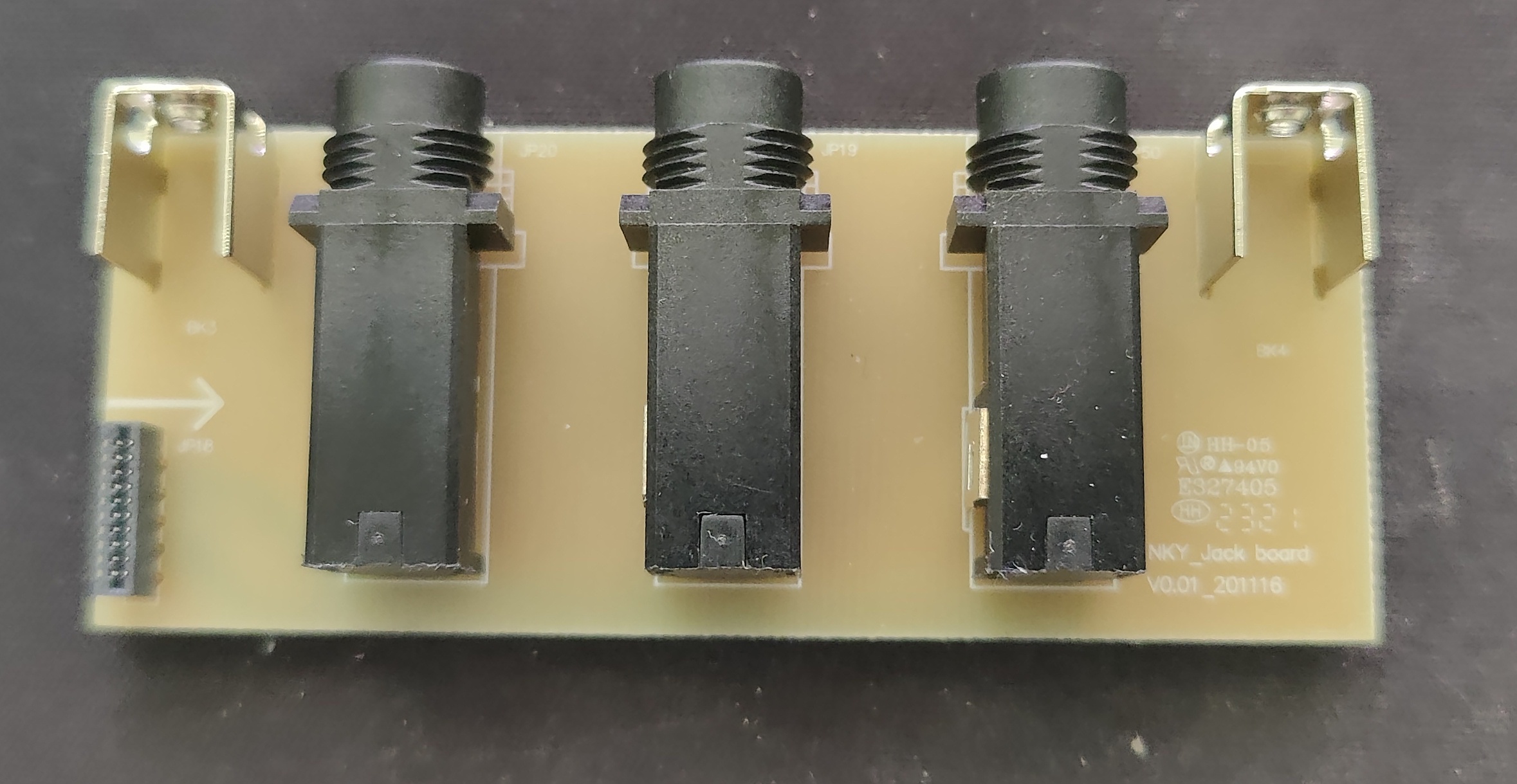
Most of the offending surface area is just PCB, but a few millimeters come from the jacks themselves. However, that’s only because the jacks are flush with the outside of the case. They could be made a few millimeters shorter by sticking out the back of the case. This is fine with me, as the function is a lot more important to me than the aesthetics.
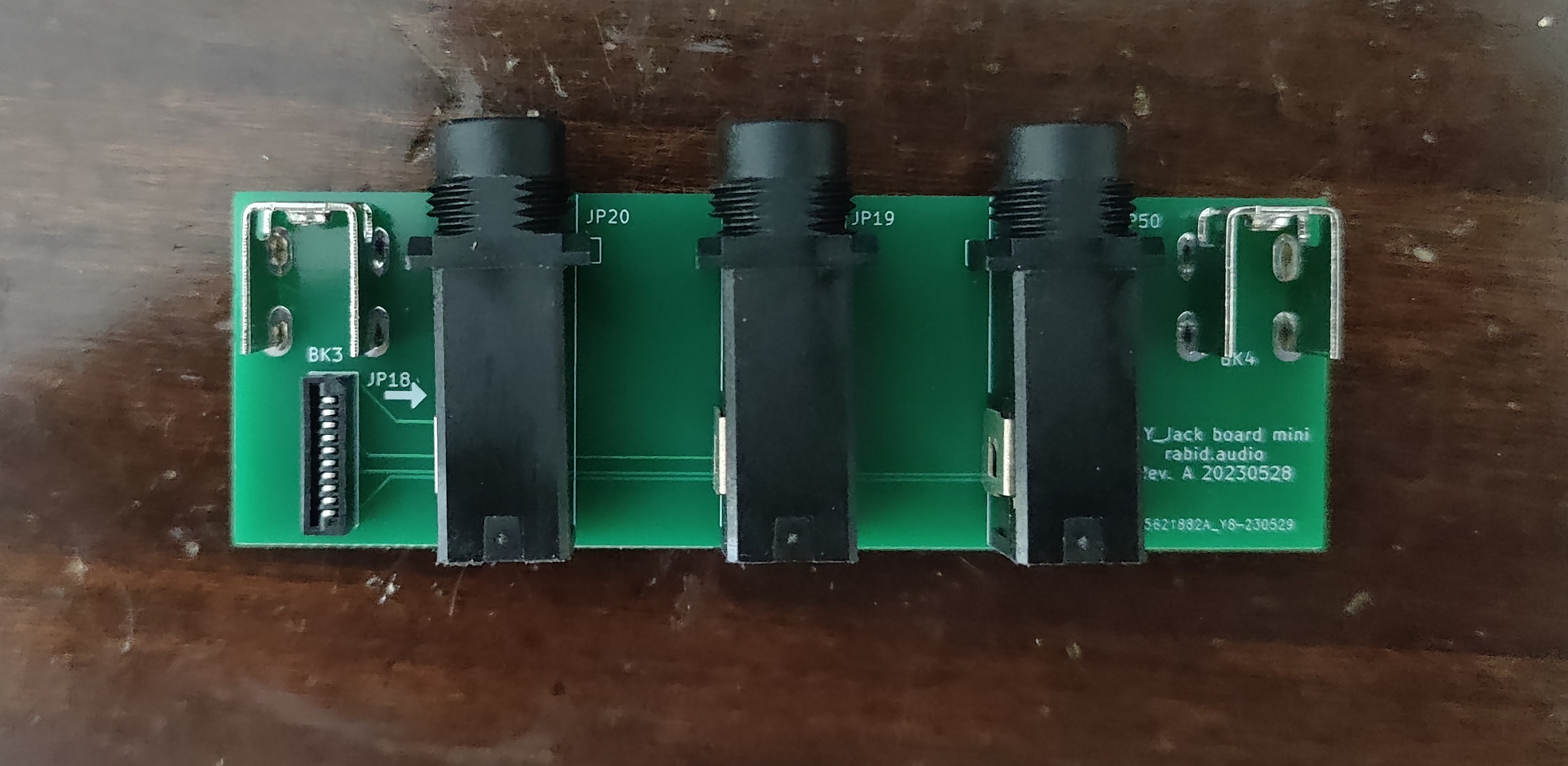
Since the board is so simple (a 10-pin, 1mm pitch ribbon cable, 3 jacks, and a pair of screw mounting brackets), I decided to just re-design a replacement myself, one that actually fits in the case.
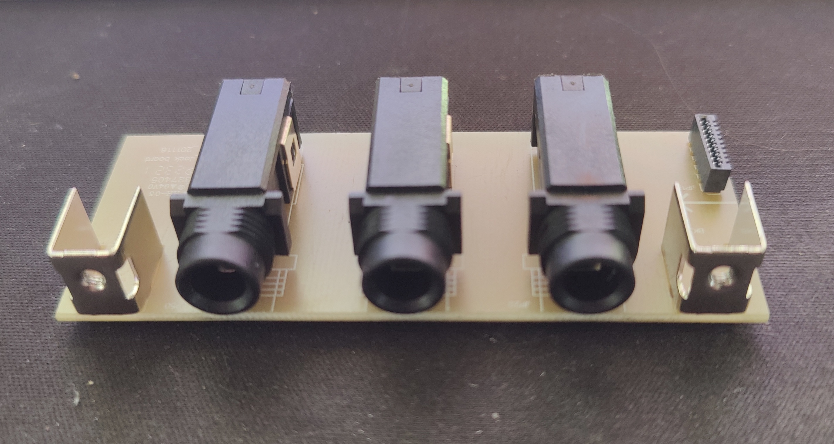
I found what I think is a compatible flat flex cable connector, as well as footprints for the jacks. Whipped up a little board in KiCad in an afternoon. Source and gerber files on GitHub.
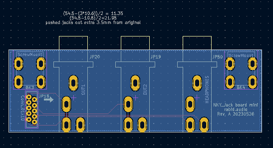
I was hoping to also do a single-layer board, but I realized laying it out that the wiring they used can’t be done without at least one pair of traces crossing, so I went ahead and made it two layers instead. I also went ahead and pushed the jacks a few millimeters out the back of the case, gaining a little bit more space.
My plan is to salvage the jacks and mounting brackets from the existing board, but I decided to buy the connector because all those pins would be hard to desolder cleanly and I wanted to be sure it would fit the design. The connector is $0.16 on DigiKey and a single board is $0.40 on JLCPCB. Unfortunately with minimum order quantities and shipping that comes out to $30 (plus an additional $20 if it turns out my PCB design is wrong and I have to run a second batch!). Still, worth it for a good kit IMO.
Boards should arrive in about a week. I’ll update here with pictures of the final assembly.
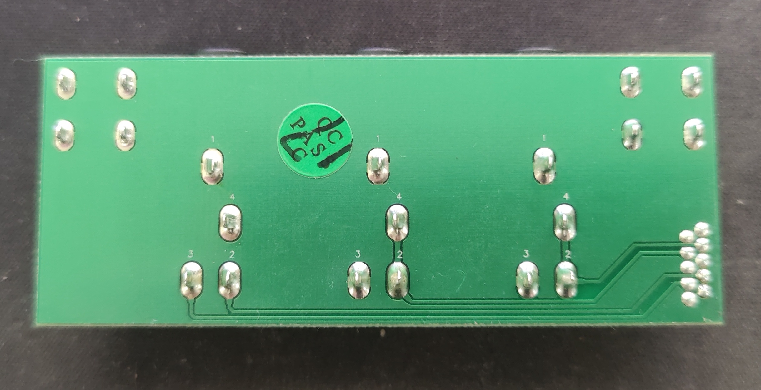
Update: 2023-06-01: Boards and parts arrived today. De-soldering the screw mounts ended up being more difficult than expected, because it’s a big metal hunk that absorbed all the heat. I ended up first using the heat gun for a solid minute to get the part pretty hot and then the iron was able to heat the pads up enough to melt the solder to be sucked up.
The board worked flawlessly. It sticks into the rack by a millimeter or so, but not enough to get in the way of any of my modules. Long shot but if anyone has one of these keyboards and wants to do the same, reach out and I’ll send you one of my PCBs at-cost.