Approximating audio taper pots
- electronics
Often in audio electronics, most relationships are non-linear. Both loudness and pitch are perceived by humans logarithmically. Audio-taper pots (the more common name for log-taper) are the most common solution to handle this. The resistance varies logarithmically rather than linearly, so that for example as you turn a volume knob, the perceived loudness is linear.
But sometimes audio-taper pots in a particular value are difficult to find. Manufacturers will produce pots in a number of different resistances for linear taper, but only a handful of resistances in audio taper. Or maybe you just want to use linear potentiometers you already have on-hand. Can you use a linear taper in place of an audio taper? Yes! In this post I’ll show you how. But first let’s talk about audio taper in depth.
Audio taper
Most “audio-taper” pots sold are not actually logarithmic, but instead use a piecewise-linear approximation. These are normally marked as “A” taper (e.g. A100K), as opposed to linear (e.g. B100K).
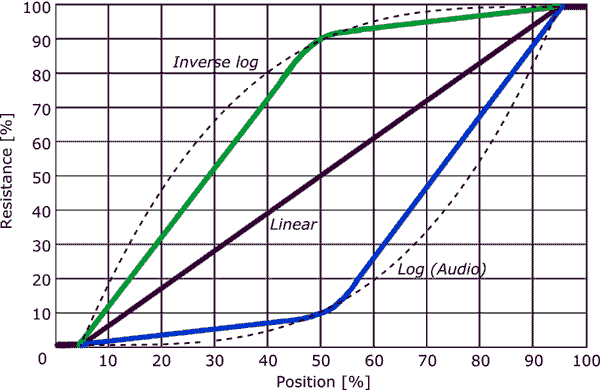
Source: eepower.com
Logarithms can have different slope steepness. Specifically for audio, the transition point at half-turn is at about 10-20% of the total resistance (that is, say 15% of the resistance changes in the first half-turn, and 85% changes in the second half).
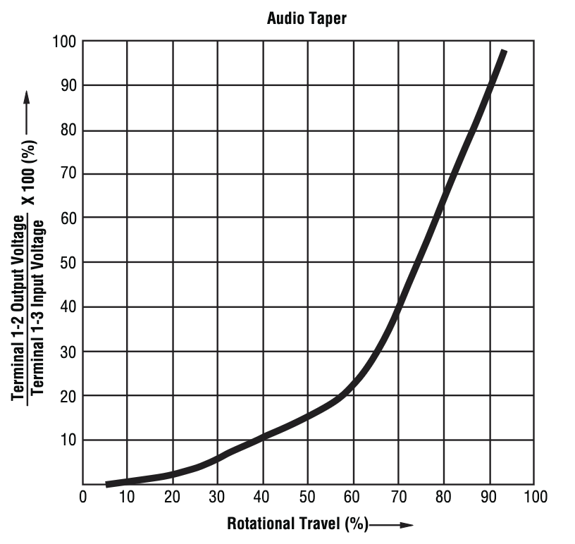
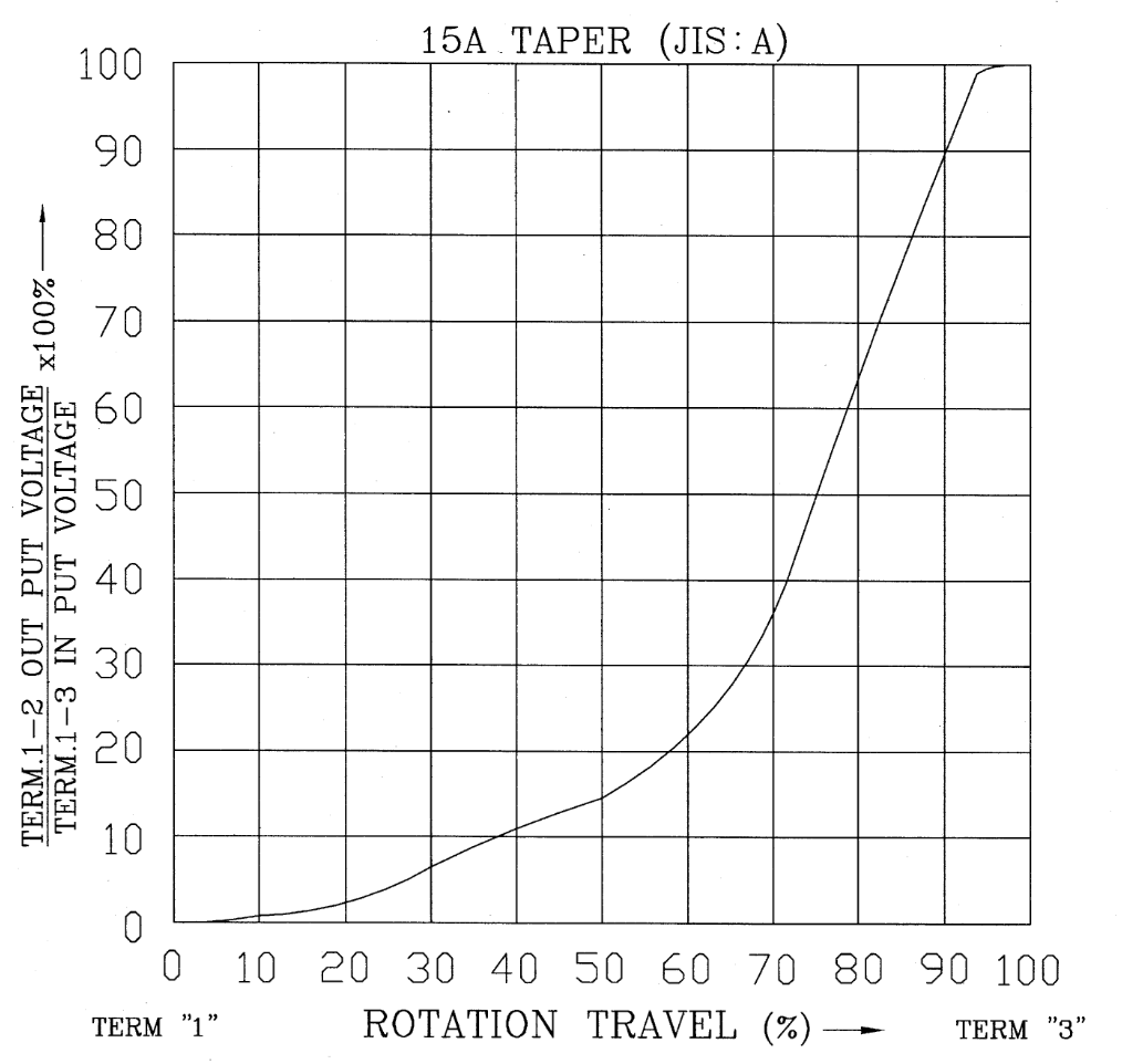
Here’s the taper graphs from a Bourns slide taper pot (PTA) and an Alpha 9mm pot (RD901), where you can see they are a little better than piecewise-linear, but still an approximation.
Parallel resistance
When putting resistors in parallel, the formula of the combined resistance is
$$ R_{1}||R_{2} = \frac{1}{ \frac{1}{R_{1}} + \frac{1}{R_{2}} } $$
If one resistor is variable while the other is fixed, this creates a non-linear relationship. Let’s add a fixed resistor value in parallel with a linear pot, like so:
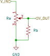
Furthermore, let’s assign p to to be the position of the pot in the range 0 to 1 (where 0 is fully counter-clockwise, and 1 or 100% is fully clockwise). For reasons that will be clear later, let’s define a ratio between the resistors r such that
$$ R_{b} = r R_{a} $$
Then, the formula for the voltage divider ratio is
$$ \frac{ V_{out} }{ V_{in} }(p) = \frac{ R_{b}|| p R_{a} }{ (1-p)R_{a} + R_{b}|| p R_{a} } $$
$$ = \frac{ r R_{a}|| p R_{a} }{ (1-p)R_{a} + r R_{a}||p R_{a} } $$
\[
  \newcommand{\ppl}[2]{ \frac{1}{ \frac{1}{#1} + \frac{1}{#2}} }
  = \frac{ \ppl{r R_{a}}{p R_{a}} }{ (1-p)R_{a} + \ppl{r R_{a}}{p R_{a}} }
\]
I’m very liable to make mistakes when doing math by hand, so instead let’s just dump this in a computer. We find the simplified form:
$$ \frac{ V_{out} }{ V_{in} }(p) = \frac{ p r }{r - (p-1) p} $$
This makes intuitive sense. When r is very large (i.e. Rb >> Ra), the equation approximates p (i.e. a normal linear pot). When r << 1, the equation approximates 1/(1-p).
We can then solve for the value of r which best approximates a log function.
What ratio to use?
There are actually several approaches we can use to fit. The simplest is to use the 15% resistance at 50% turn inflection point of the piece-wise linear approximation and solve for r:
$$ 0.15 = \frac{ 0.5 r }{r - (0.5-1)*0.5} $$
$$ r = 0.107143 $$
That is, Rb should be about 10-11% the size of the total resistance of our linear pot.
Another approach would be to solve for the actual behavior we want: a linear change in position causes a linear change in gain when measured in decibels (dB). In order to do this, we need to know what the bandwidth (i.e. dB range) of a typical audio taper pot is.
Using the 15% at half-turn data point again, a gain of 0.15 is 20*log10(0.15) is about -16.5 dB. Since that’s half the turn and we assume the pot is linear in dB, than the total bandwidth must be 33dB. That gives us a target formula of
$$ \frac{ V_{out} }{ V_{in} }(p) = -33(1-p) \mathrm{dB} = 10^{\frac{-33*(1-p)}{20}} $$
Thus, we can compare the fitness of various tapers to this target formula. Since our functions are non-linear, we can’t use least-squares, so we’ll use the root-mean-squared-error (RMSE) formula instead:
$$ \sqrt{ \frac{1}{n} \sum_{i=1}^{n} (y_{i} - \hat{y}_{i})^2 } $$
To do this, I made a spreadsheet which compares this parallel resistor solution with a linear-piecewise and a real audio-taper (by extracting numbers from the Alpha RD901 datasheet).
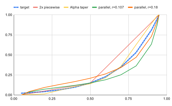
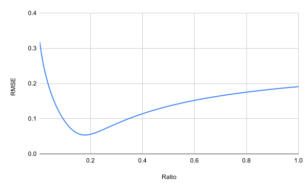
Notice that the 10% ratio solution we calculated first has comparable error to piecewise. By establishing a function that given a ratio r outputs the RMSE, we can apply gradient descent (below) to find the optimal ratio to be about 18% (more precisely 0.17846). This error is close to the error of a real audio-taper Alpha pot.
| Solution | RMSE |
|---|---|
| linear piece-wise | 8.68% |
| Alpha | 4.06% |
Parallel, r=0.107143 |
8.10% |
Parallel, r=0.18 |
4.87% |
Load Resistance
Here’s a problem that is closely related: the resistance of the load of your pot. When a pot is being used as a voltage divider, it’s middle terminal will have a voltage relative to the input proportional to the turn position, if there’s no load. By adding a load, we’ve effectively accidentally created this non-linear behavior.
A circumstance where you might run into this is when you have a volume knob running into a subsequent low-impedance network, like a passive filter stack or a speaker. Often you’ll need a high input-impedance buffer (such as an op-amp or transistor amplifier) to “copy” the voltage onto the next stage.
But if you’re trying to minimize parts, it might not be ideal to add a buffer here. For example, let’s say you have a volume pot that then goes to a summing amplifier (shown below):
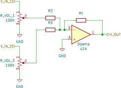
What should the values of R1 and R2 be? Here since pin 2 on the opamp is a virtual ground, we’ve created the same topology from above. We can use this same formula to see the effect of those load resistors on the transfer function.
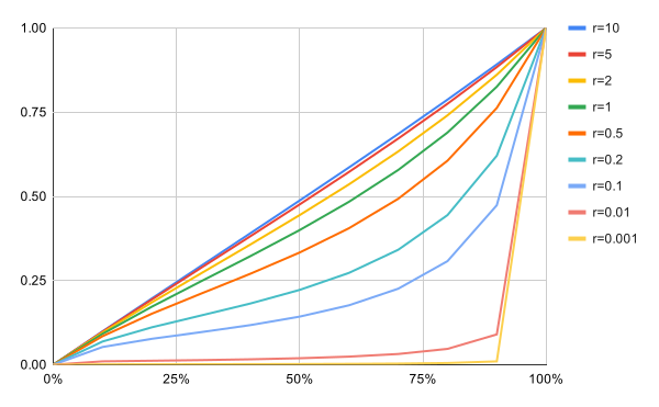
As you can see, if R1 and R2 are at least 10x our pot resistance we should see a linear behavior. Even a ratio of 1-2x remains fairly linear. On the other hand, if we wanted a logarithmic taper (which we likely would in this example since we are dealing with volumes), we can go ahead and use a ~20% value instead (say, 22k to match our 100k pots) combined with linear instead of audio-taper pots, and avoid having an additional buffer between our volume and our summing amplifier.
Conclusion
In short, if you want to convert a linear taper pot into an audio taper, you can add a resistor in parallel that’s about 18% of the total pot resistance. For example, if you have a 100K pot, use an 18K resistor (or even a 15K or 22k, these will still give you good performance). You can experiment with values anywhere from 5% to 50% to see what sounds good to your ears, particularly if you want more control in the low range or the high range.
Code
Here’s some ruby code I used to compute the optimal solution:
BW = -33.0

def db(val)
    10.0 ** (val.to_f / 20.0)
end

def target_fn(pos)
    pos.map { |p| db(BW * (1-p)) }
end

def parallel(r, p)
    (r*p)/(r - (p-1)*p)
end

def fn(r, pos)
    pos.map { |p| parallel(r, p) }
end

def rmse(target, actual)
    Math.sqrt(target.zip(actual).map { |t, a| ((a-t) ** 2) }.sum / target.count.to_f)
end

def ratio_error(r)
    pos = (0..1).step(0.01)
    rmse(target_fn(pos), fn(r, pos))
end

ratios = (0..1).step(0.005).drop(1)

fits = ratios.map { |r| [r, ratio_error(r)] }.to_h

fits.each { |r, e| puts "#{r}\t#{e}" }


# NOTE: an LLM generated the following functions

# Approximates the gradient of an arbitrary multi-variable function using central differences
def numerical_gradient(f, point, h = 1e-5)
  point.map.with_index do |_, i|
    point_forward = point.dup
    point_backward = point.dup

    point_forward[i] += h
    point_backward[i] -= h

    # Central difference formula: (f(x + h) - f(x - h)) / (2 * h)
    (f.call(*point_forward) - f.call(*point_backward)) / (2.0 * h)
  end
end

def gradient_descent(start_point, learning_rate: 0.05, iterations: 1000, tolerance: 1e-6, &f)
  point = start_point.dup

  iterations.times do |i|
    grad = numerical_gradient(f, point)

    # Calculate gradient magnitude to check for convergence
    grad_magnitude = Math.sqrt(grad.sum { |g| g**2 })
    if grad_magnitude < tolerance
      puts "Converged successfully at iteration #{i + 1}."
      break
    end

    # Step in the opposite direction of the gradient
    point = point.zip(grad).map { |val, g| val - learning_rate * g }

    # Print progress every 100 iterations
    if (i + 1) % 100 == 0 || i == 0
      cost = f.call(*point)
      formatted_point = point.map { |v| v.round(4) }
      puts "Iteration #{i + 1}: Point = #{formatted_point}, Cost = #{cost.round(6)}"
    end
  end

  point
end

min_r, = gradient_descent([0.2]) { |(r)| ratio_error(r) }
puts "optimal solution: r=#{min_r}, rmse=#{ratio_error(min_r)}"