Crunch Time
- hardware
Note
This is an old post or draft which was migrated from my old blog. It may have broken links, and it definitely has questionable opinions. Consume at your own risk.
I’ve tried out a few bass guitar distortion effects pedals in the past (as well as a few designed for guitar), but none of them really sounded great. Mostly they killed all the punchiness of the bass so that it just sounded flat and empty. Then one day a few years ago, I plugged my (budget, nothing special) electric bass and was surprised to find this smooth, crunchy, synth-like distortion sound coming out, with no other effects plugged in. It took me a while to figure out, but eventually I learned what happened was the 9V battery for the active pickups had gotten pretty old, and was in a sweet spot to deliver just enough voltage for the amplification circuit to still function but clip ever so slightly. I replaced the battery, but I wanted a way to get that sound on demand.

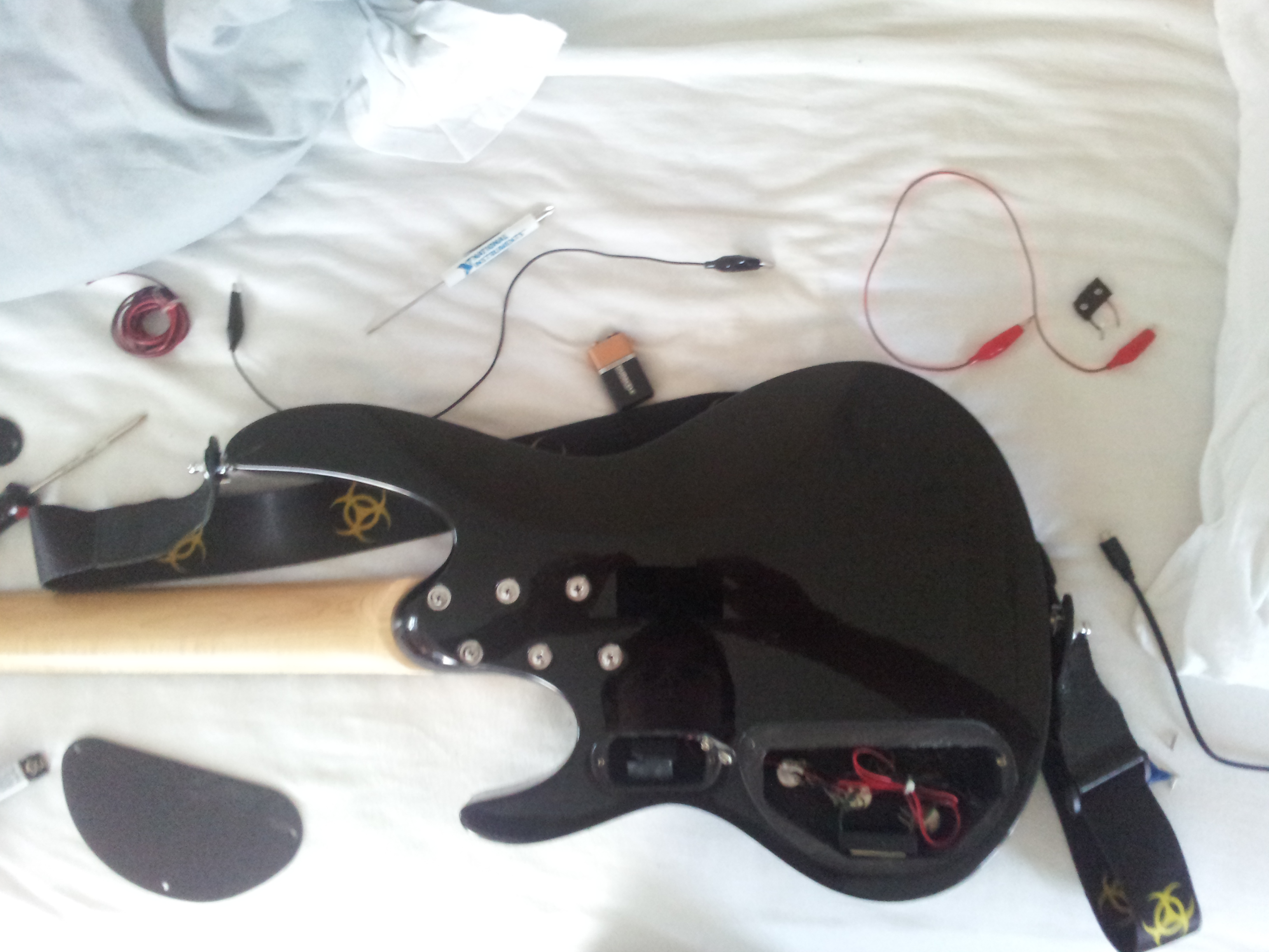
For a while, I had a weird attachment with a potentiometer hanging out of the bottom of my guitar by a few wires, but this was not a usable or pretty solution, so I removed it and forgot about it. But today I was reminiscing, and decided I could probably whip up a better solution.
One issue is the sweet spot for the voltage is in a narrow range around 1.5V. Too low, and the active circuitry shuts off, and two high and it functions like normal. Also, as the battery voltage sags, the knob position for the spot moves. I found it very hard to dial in just the right amount with a potentiometer tracking the voltage between 0 and 9V. The ideal control would be a choice between 9V and a sweep from around .5V to 2.5V. One option was to use a regulator such as the LM317 to regulate the voltage down to 2.5V and then sweep 0 to 2.5V. Unfortunately I didn’t have a switch pot on hand, and a regulator is a constant current drain, which would probably eat the battery faster.
The ideal solution would be a sweep which swept the sweet spot range slowly and then quickly accelerated to the 9V range at one end. I ended up accomplishing this using diodes. A very simplified model of an ideal diode is that it has zero resistance if the voltage is above a certain threshold and infinite below. For most diodes, this is around 0.6V. We can exploit this feature to get a nonlinear response out of a linear potentiometer. I played around in a circuit simulator for a while, and eventually came up with this.

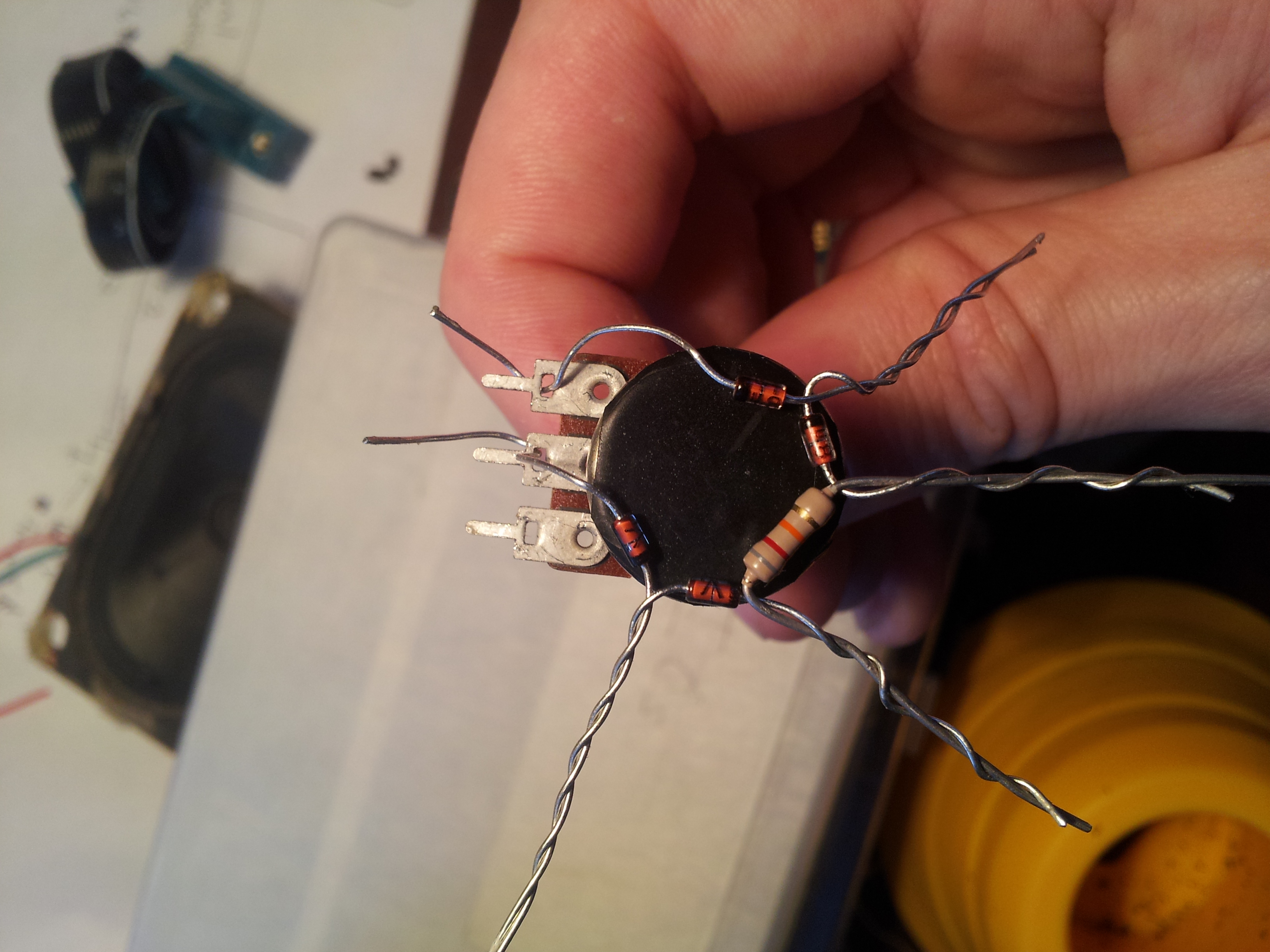
The x axis is wiper position (0 to 100%). The upper graph is the output voltage, and the lower graph is the current sunk (that is, the current that) wouldn’t go out to the rest of the circuit. Notice the gradual voltage increase through most of the turn, and then the quick jump to 9V at the end. At first, I had a circuit with 4 diodes (thinking that 4*0.6 = 2.4V would be important to set my critical range), but after some experimentation, this seemed to work better. Below is an image of the earlier circuit, but the mounting I did for the final version was essentially the same, just with different components.

I decided since the tone pot (which I believe is a simple high-pass filter) only really sounded good full-on anyway, I’d keep that pot inside the guitar, and put my new distortion control through the body for use while playing.

You can hear a sample below. Unfortunately the microphone on my old phone didn’t do the tone a lot of justice, but you can get an idea.
