Princeton amp repair
- music tech
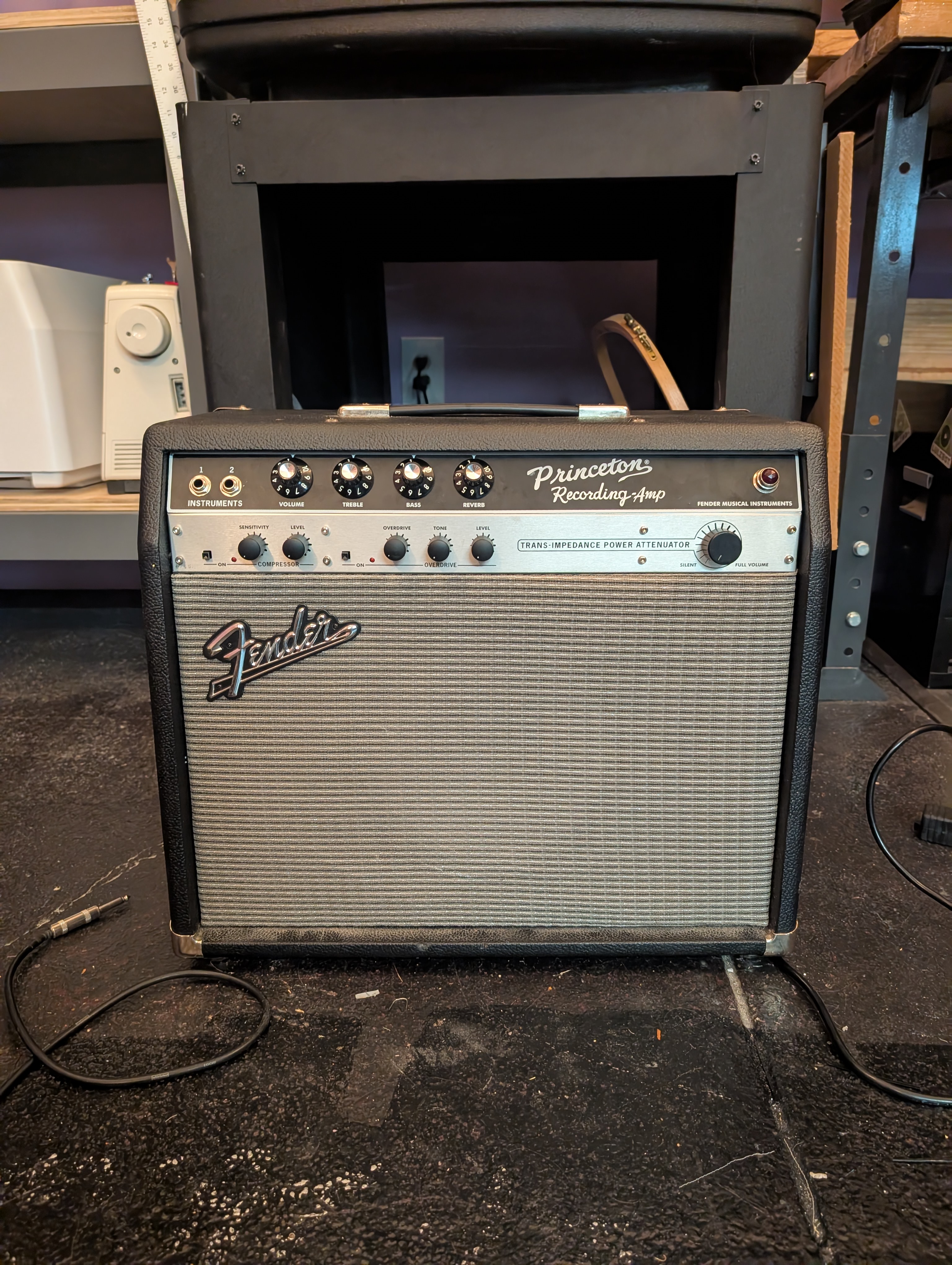
I mentioned a few posts ago that friend of mine has always dreamed of having a Fender Princeton Reverb. Well they found an amp in need of repair online and asked if I could fix it. The seller reported the attenuator not working, which I thought was strange (I don’t recall seeing an attenuator in the schematic) but I said sure, I could probably fix it.
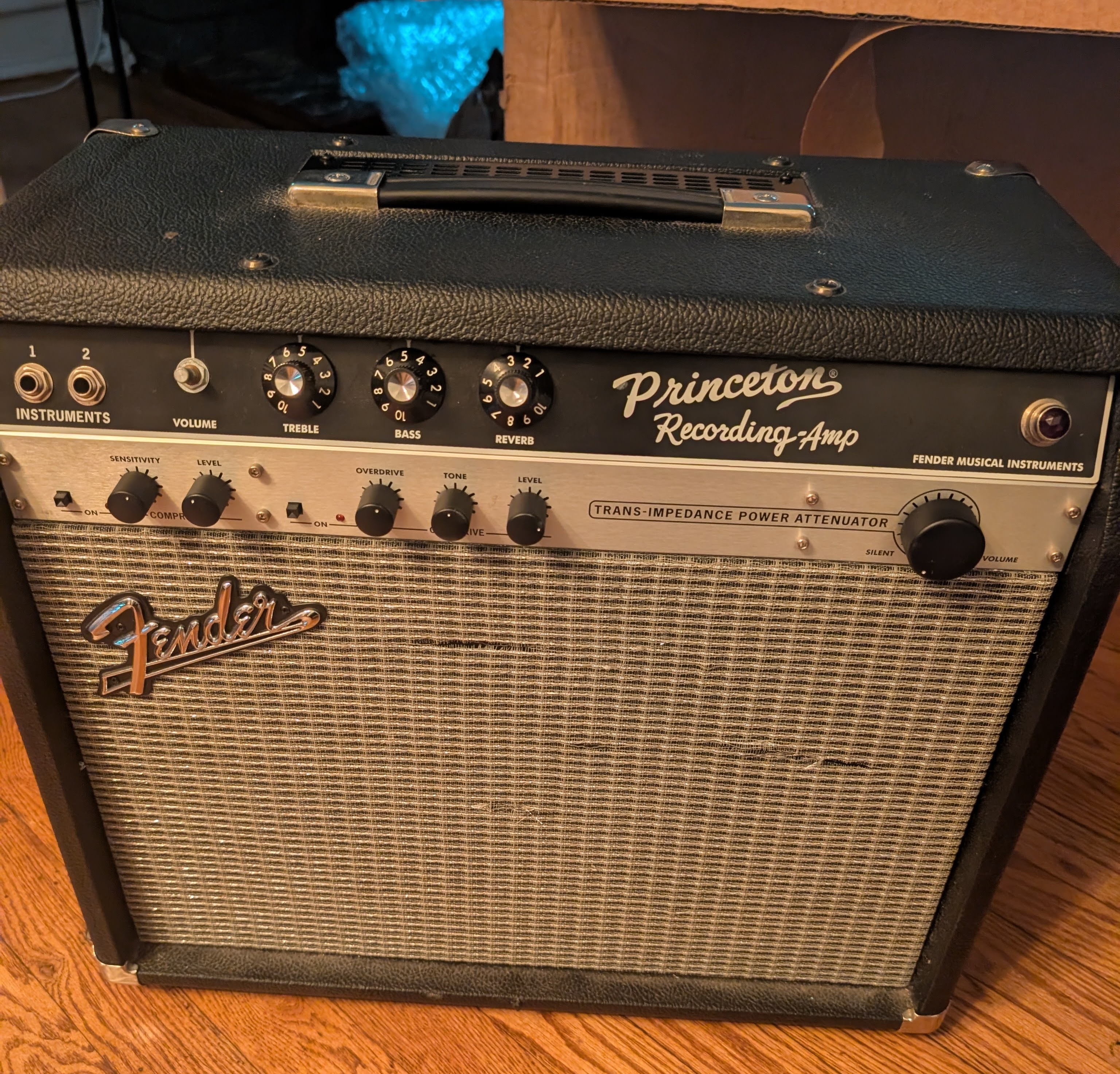
They bought it and mailed it directly to me. Turns out it’s not a classic Princeton Reverb, but rather a “Princeton Recording Amp.” This is a hybrid amp from the mid-aughts that uses tubes for the signal path but solid state analog and digital stuff for some modern features. Fortunately the schematic is available on MojoTone. It’s main feature is a “trans-impedance amplifier” that allows running the amp at lower volumes while keeping the tone of driven tubes. The circuit is incredibly complicated, but we’ll get to that later. The knob that changes the max volume of the amp was partially not working. It’s not a continuous potentiometer but rather a 16 position switch that steps through several volume levels. Some of the positions were working and some were not. And it would loudly click the speaker when switching between them. Part of the way it works is using relays, so my immediate hunch was that one or more of the relays had failed.
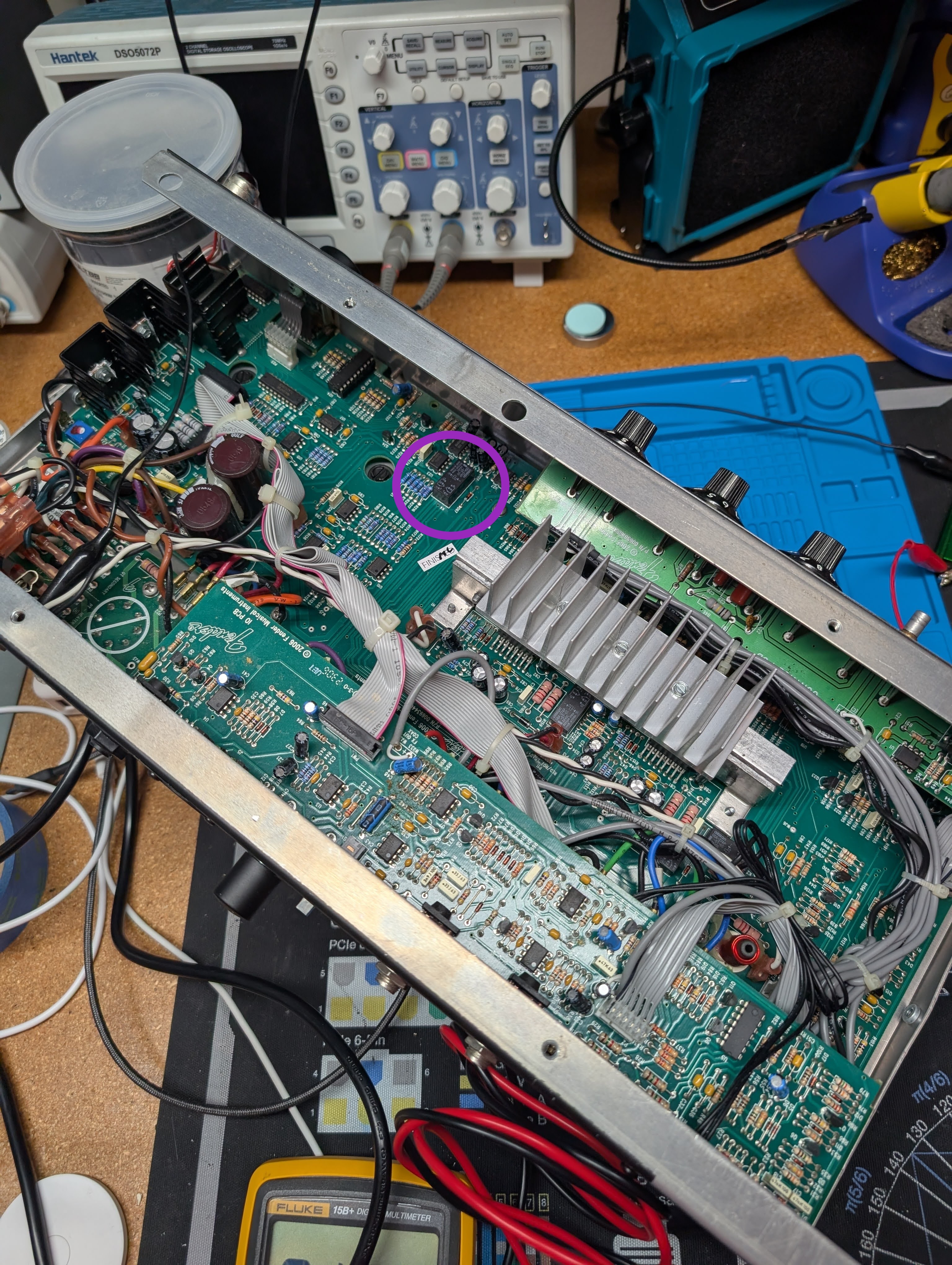
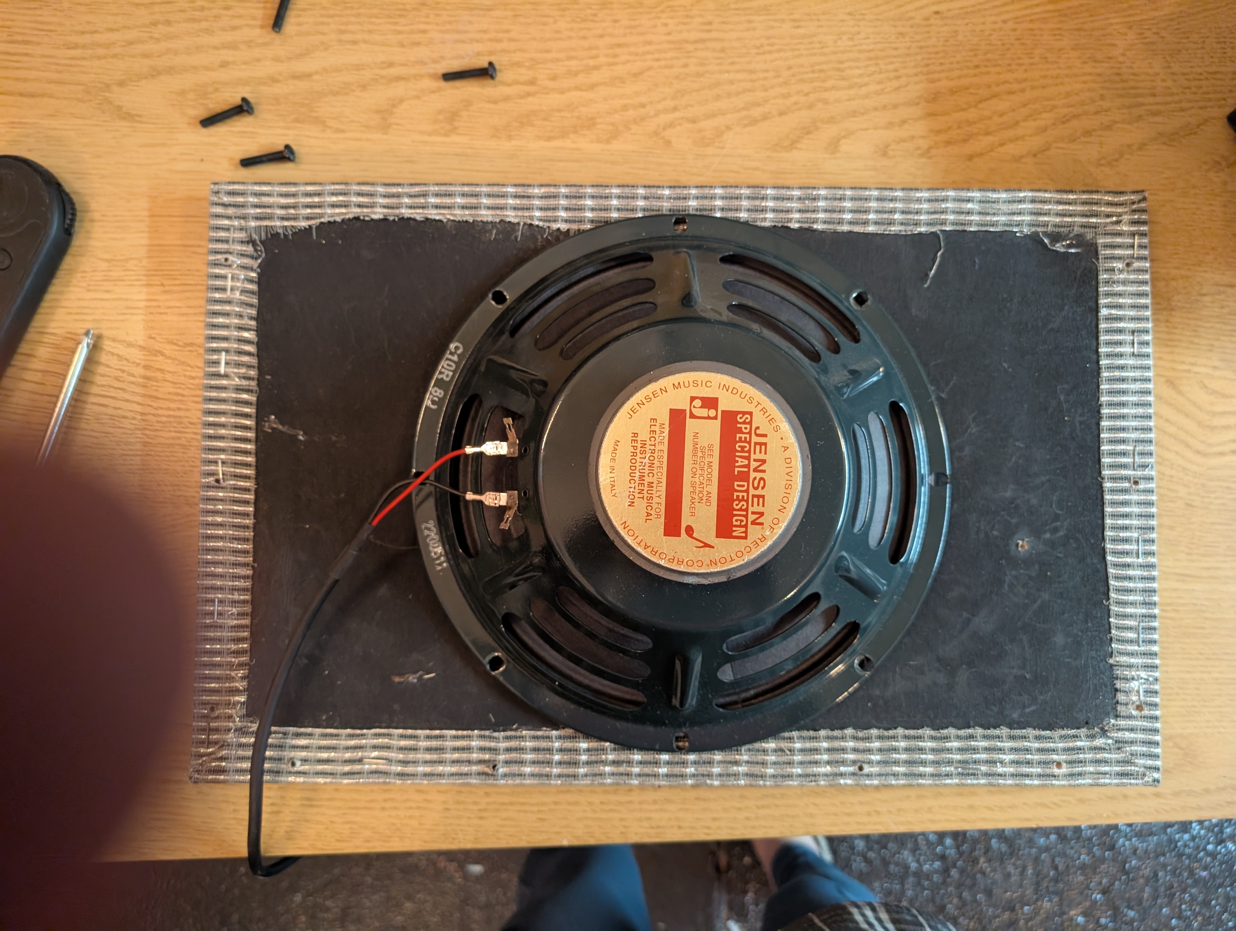
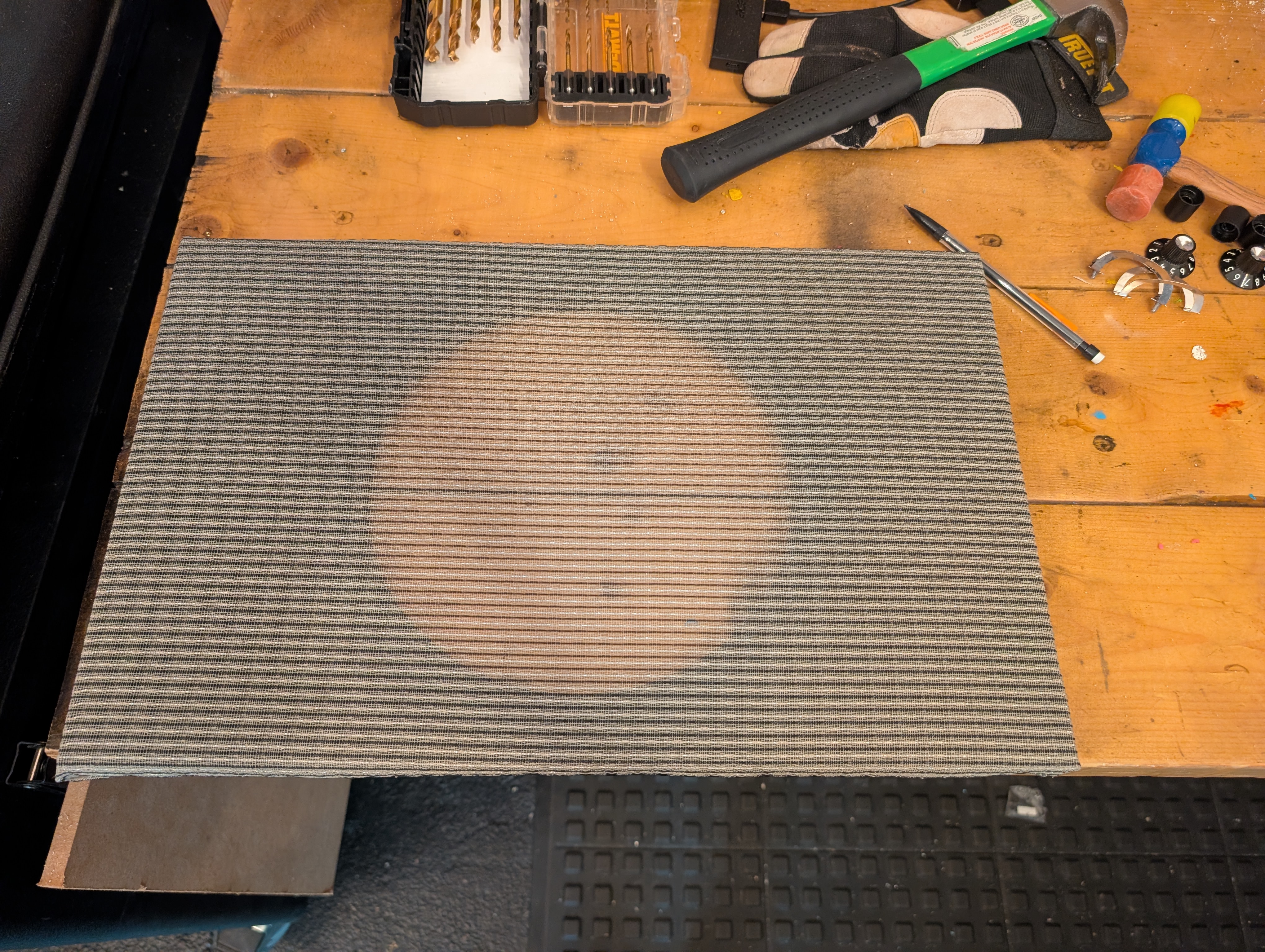
I put it on the bench, and sure enough one of the relays didn’t click when I applied voltage to the coil. The exact part was available on DigiKey for $7. I ordered 3 and told my friend this was going to be easy. I also offered to replace the speaker grill which had some tears in it, as I still had some grill fabric left over.
Trouble
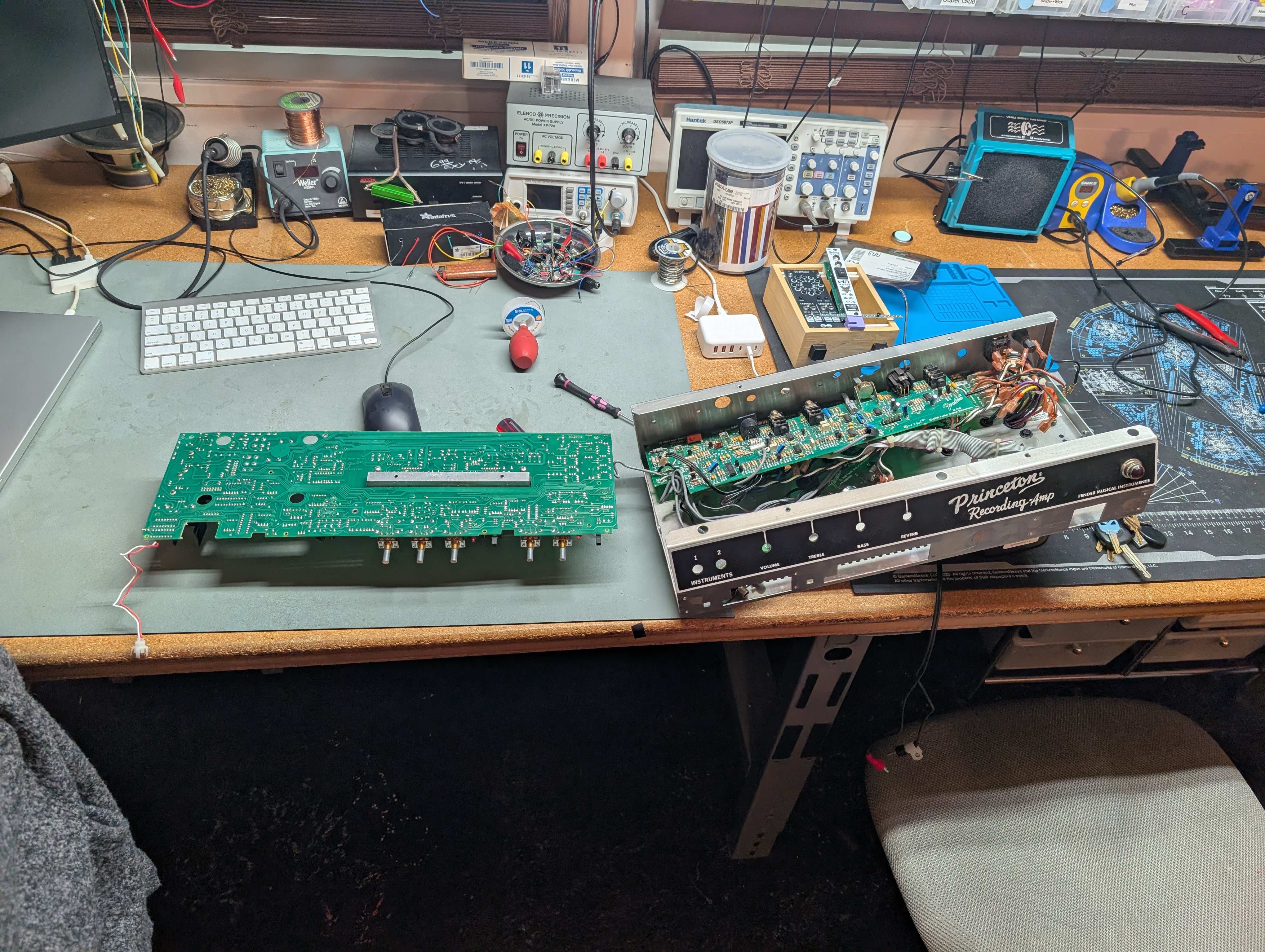
Once the parts came in it was time to replace them. Unfortunately there are 4 or 5 large PCBs in the amp, all holding each other in place through cables and panel components. I had to disassemble basically everything in order to get the main board out to flip it over.
Then getting the relay out was another pain, at least until I discovered this ChipQuik chip remover alloy stuff in the makerspace. We don’t have a rework station or oven so I was legitimately unsure how to get it out. But this stuff is incredible. It works kinda like solder but it stays hot longer. So you put a bit on each of the pins, then jump from pin to pin keeping them hot and eventually the chip will just wiggle out. Then a sucker can suck up the alloy, leaving nice clean pads.
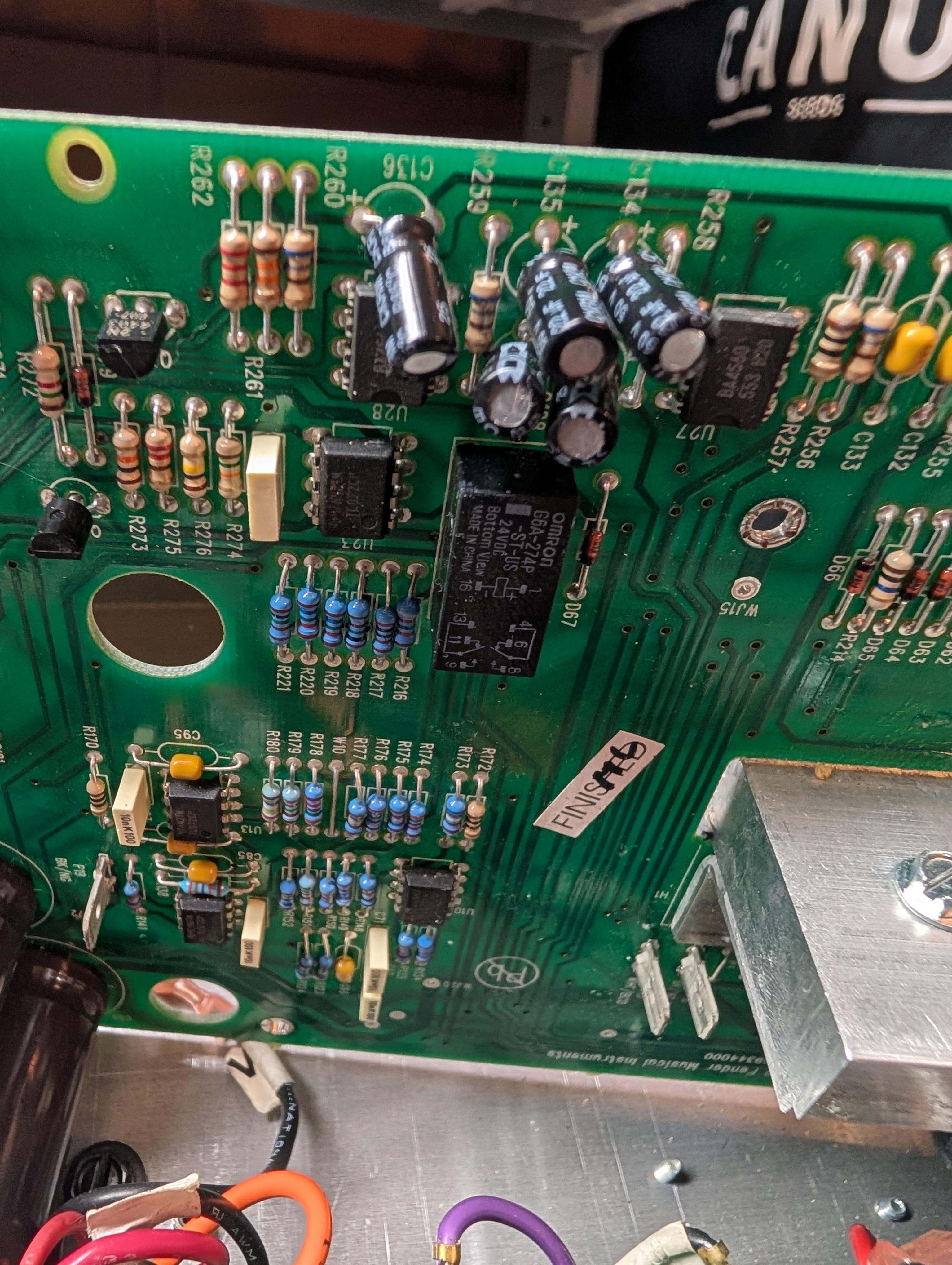
These relays are multiples of 0.1” spacing, so I used some DIP chip holders so that if it fails again it will be easy to swap without pulling the whole board out.
In the process of taking the whole thing apart, I broke wires several times and had to solder them back together. They used clips for all the power connections but audio signals used soldered coax cables which were quite fragile.
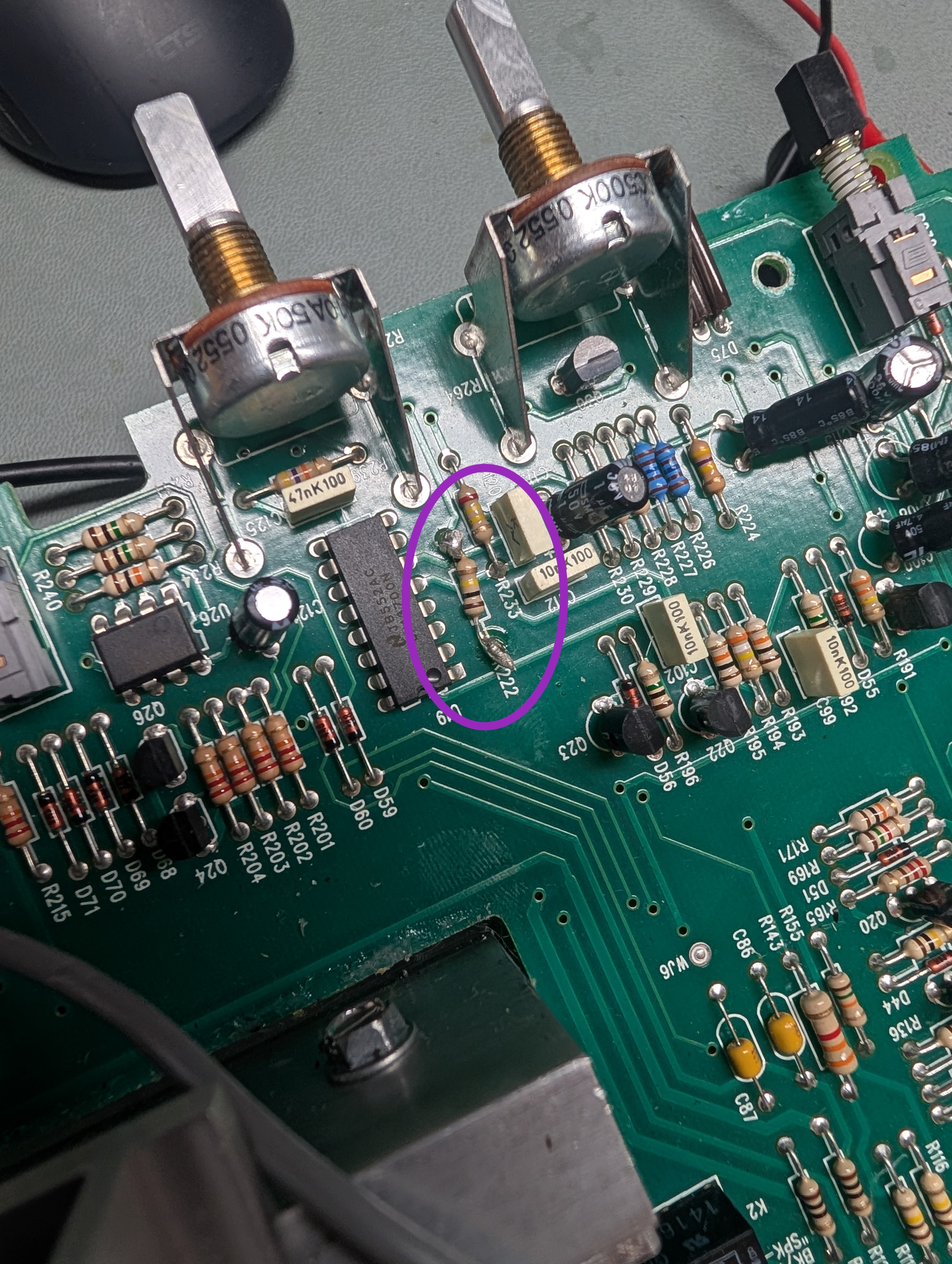
I also found a spot where a repair had been made. Someone had replaced a resistor by cutting the existing legs and soldering on top of it. That’s a reasonable solution to avoid pulling all the boards out, and one I would have used on the relays if it were possible. However, they used a 100k resistor where, according to the schematic, a 68k resistor was supposed to be. I suppose this could have been a mod but the resistor was in the I_abc control of an LM13700 OTA, which are notoriously picky about currents. I suspect someone was just being lazy with their repair, so I replaced it with the correct value.
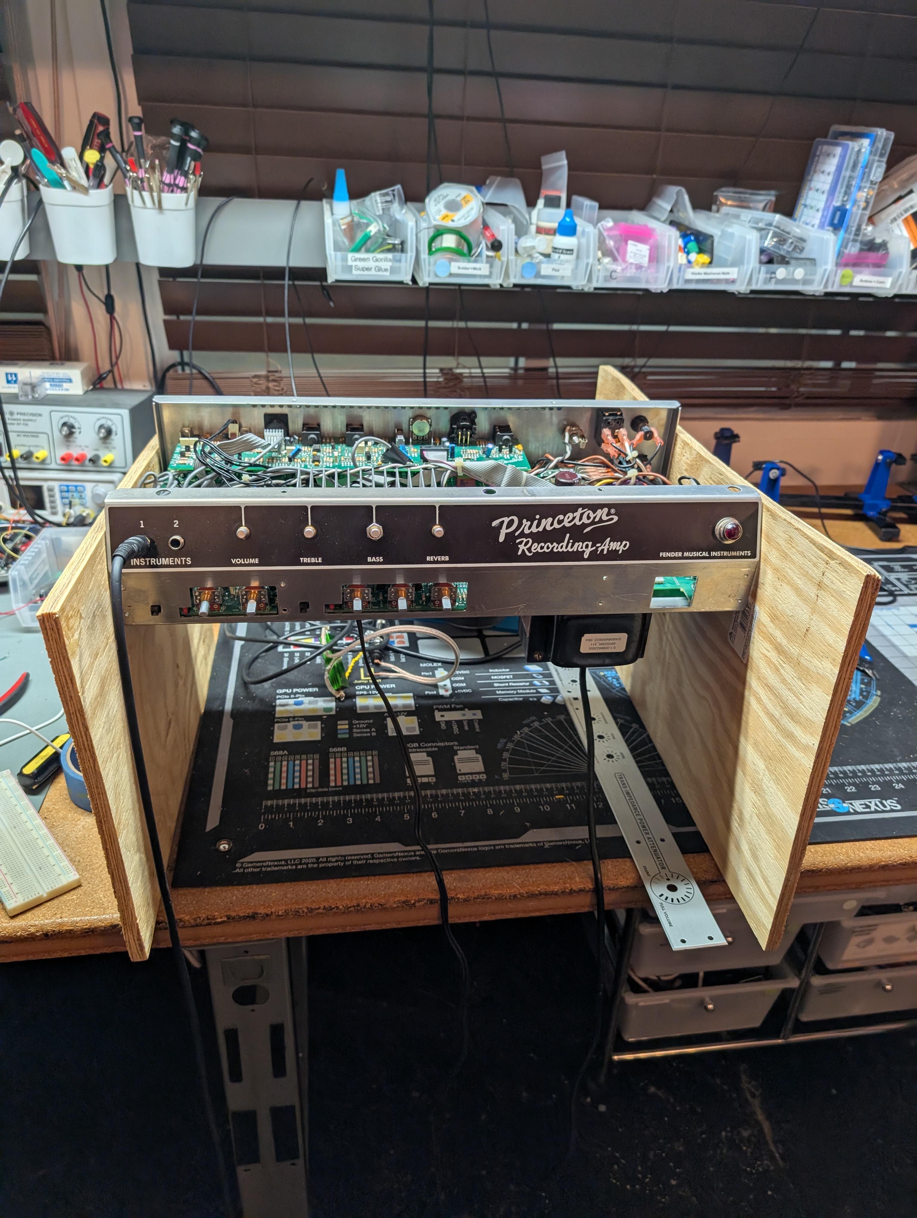
I rigged up a bit of scrap plywood to hold the amp up, allowing me to access the inside while the tubes were plugged in.
Grill: more trouble
The grill also was a pain. The grill was held in place with a combination of staples and glue. I had to pull out all the staples, which sucked. They were too small/tight for a hammer. I broke several tools trying to get something underneath them to grab them with the pliers.
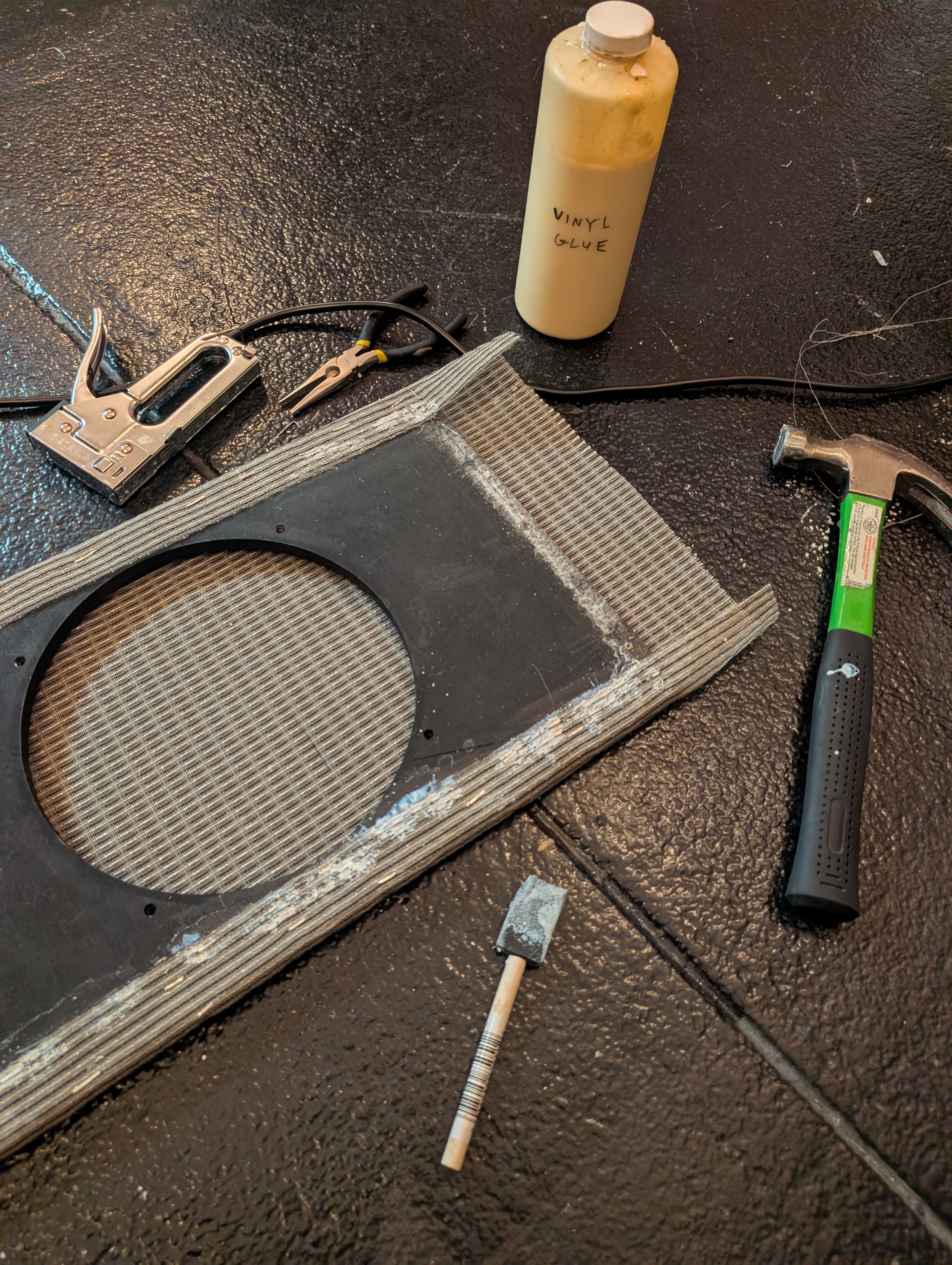
I tried to re-attach it using just glue. The existing glue (probably vinyl glue) softened under the heat gun, and I added some wood glue and then clamped it between some scrap wood. This made a huge mess and didn’t hold at all. I had to start over, applying vinyl glue and then using a ridiculous number of staples to hold it taut while the glue dried. It still didn’t turn out perfect but definitely better than the last time I did it.
Rotary encoder
With the relay replaced I powered it back up and it still only worked on some settings. A friend of mine joined me to help me debug. Together we I dove again into the schematic.
The amp has tubes, but it also has a DAC (TLC7528CN), a microprocessor (Cypress CY8C24223A), and solid state amplifiers (TDA7293). The MCU reads the rotary encoder and drives the relays and the DAC. The DAC is connected through some op-amps to the amplifiers. What’s the deal here? Is this actually a digital, solid state modeling amp pretending to be a tube amp??
Well actually, as best I can tell, they are using the solid state amps as a “reverse amplifier”, sinking current from the power tubes. This makes sense hypothetically. Imagine summing an audio signal with an inverted copy. This would result in silence (this is how noise-cancelling headphones work). By controlling the amplitude of the inverted signal, you can control the volume of the main signal. And what better way to sink a bunch of current than a solid state power amp, sinking heat into a large heatsink. I think the relays briefly route the tube output to a big wire-wound resistor load temporarily while the reverse amp is reconfiguring, keeping it from making a nasty click. Then the MCU is just there to add some logic for controlling relays and the amount of current sunk from the tubes.
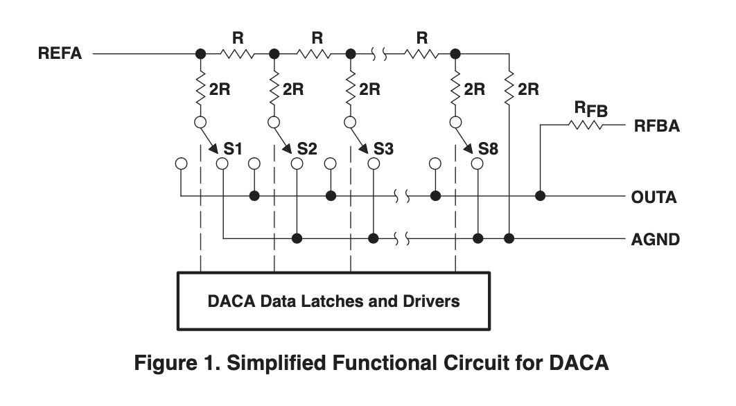
Okay, so what about the DAC? Is it digitizing the audio signal, and driving the power amps that way? Well looking at the datasheet, the DAC is actually implemented as a programmable resistor ladder. And the inputs and outputs are used in the feedback path of an op-amp, which leads me to conclude they are using this chip purely as a digitally-controlled resistor. So the audio signal path is entirely tube-based, with some digital and solid-state components to reduce the output volume of the amp without reducing the gain of the tubes (and thus the clipping behavior).
We checked the rotary encoder directly and several pins wouldn’t switch, indicating the encoder was the actual problem all along.
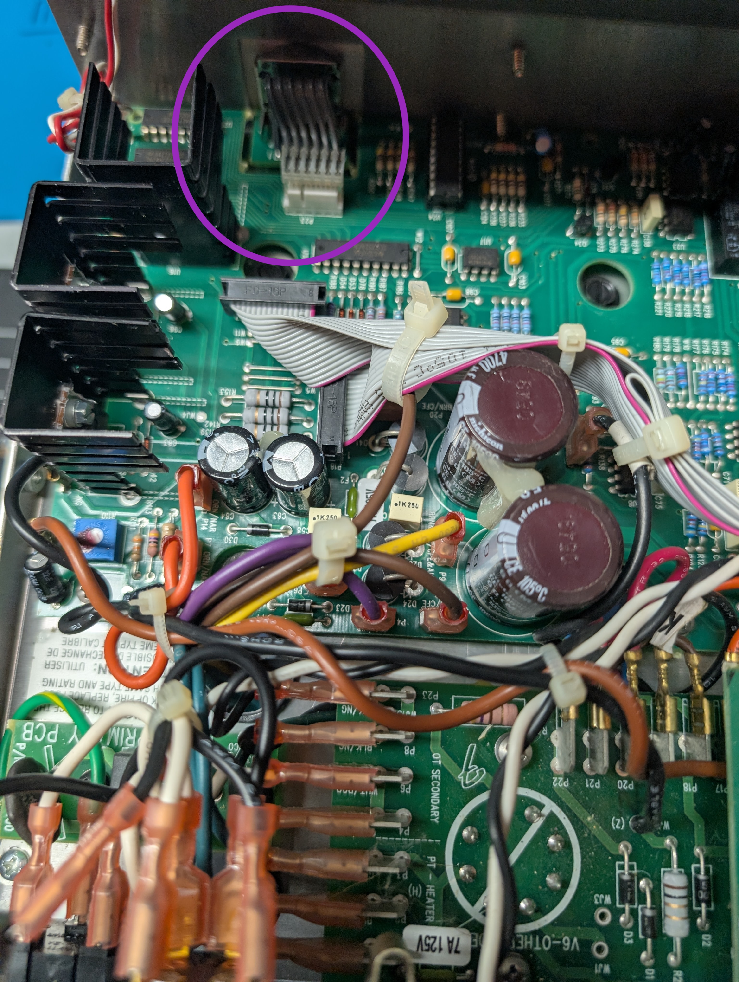
This encoder is a 16-position absolute encoder. As opposed to a quadrature encoder, which outputs a signal indicating the direction when a change happens, an absolute encoder encodes its absolute state. It has one common pin and 4 data pins, binary encoding the current position of the switch. However, these pins are not straight binary, but instead use Gray codes. A Gray code is a special ordering of binary data such that the Hamming distance between sequential numbers is always one. This reduces transmission errors in some contexts.
Some searching on the internet didn’t surface a similar part, at least not for less than $50. I reached out to Fender and they responded pretty quickly. They didn’t have any but gave me a Manufacturer and part number: Noble - SDB161EPH20F-1-4-16-16PC W/END STOP GRAY CODE. Even armed with the part number I couldn’t find one anywhere online.
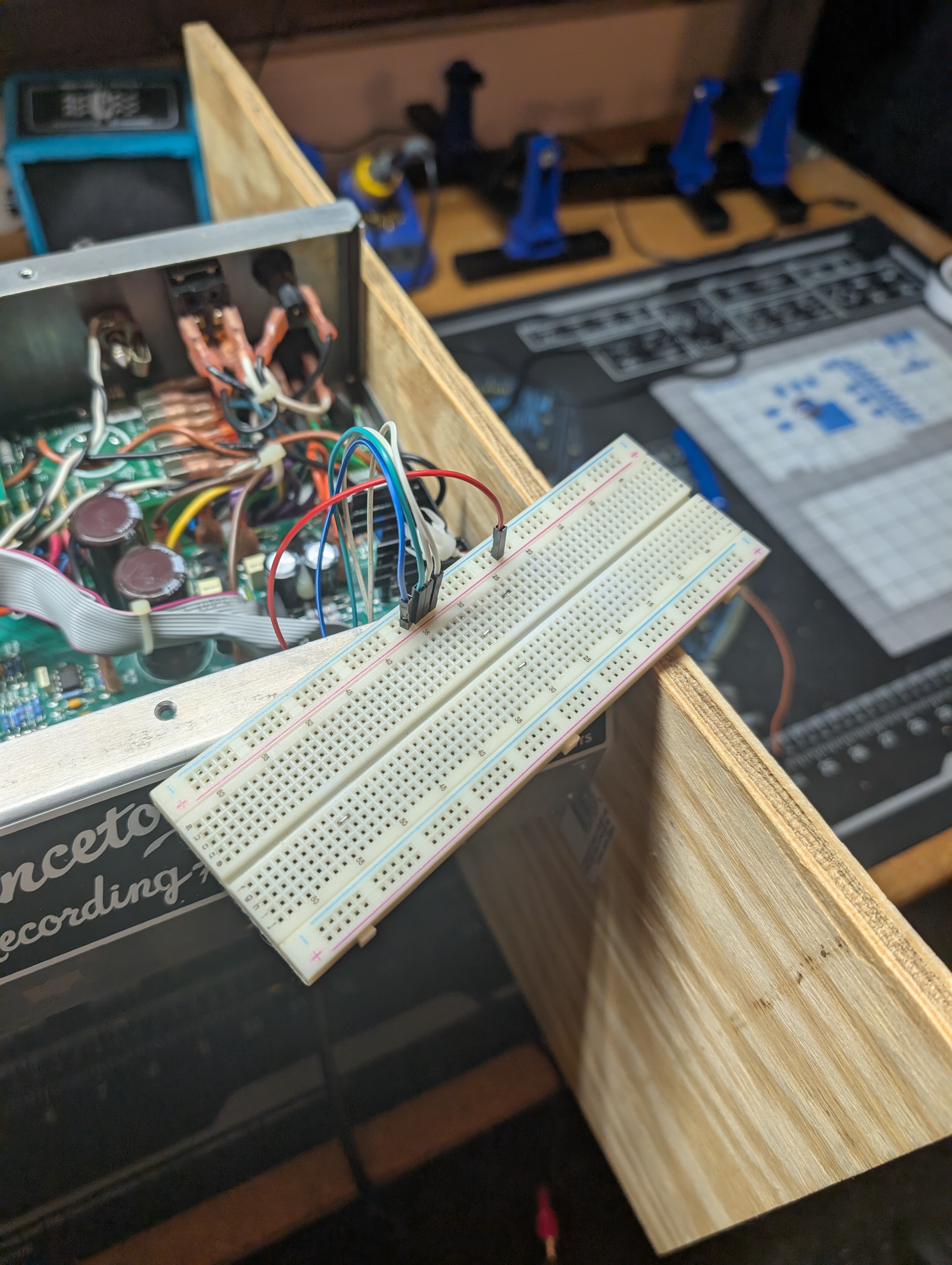
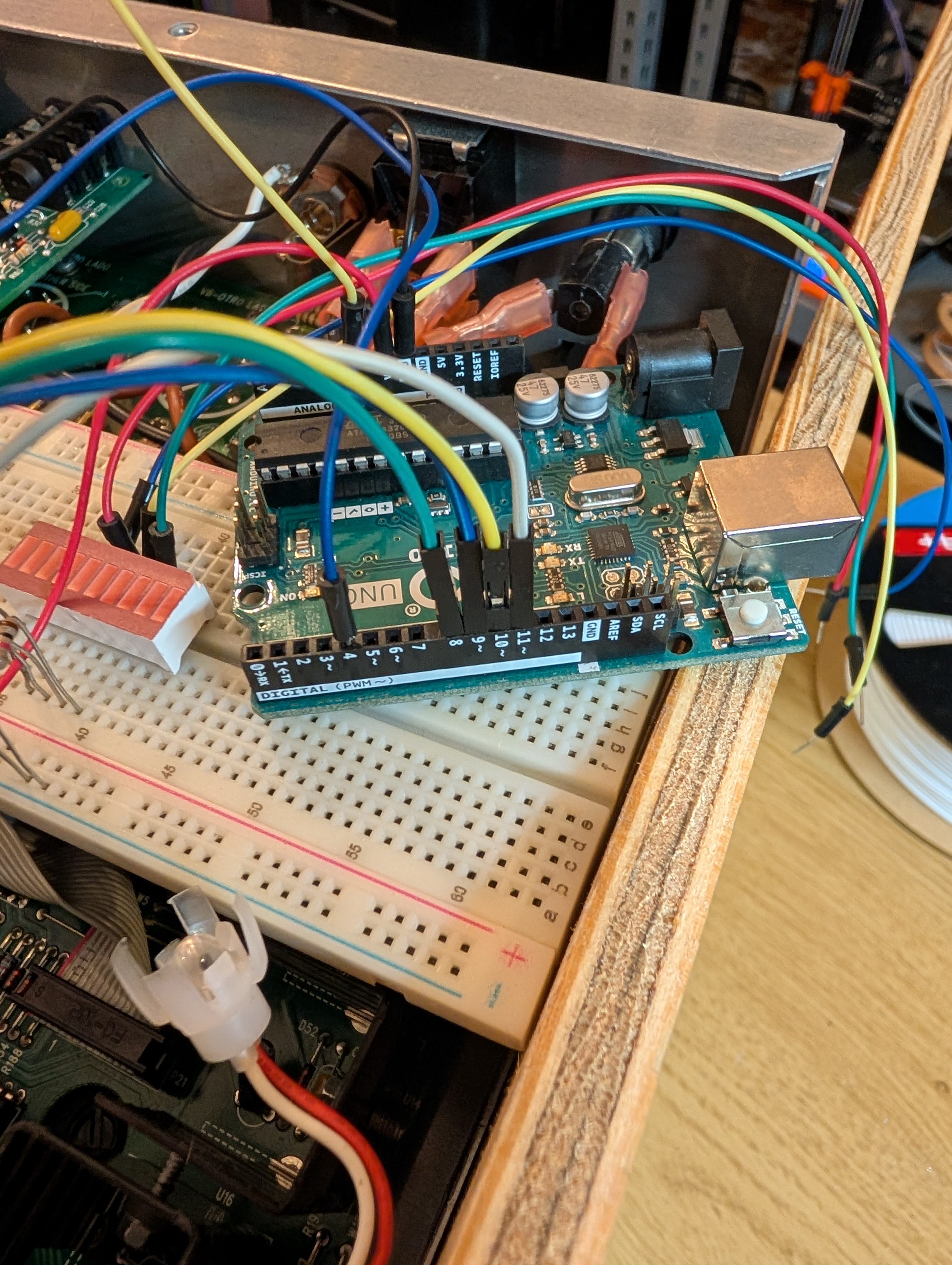
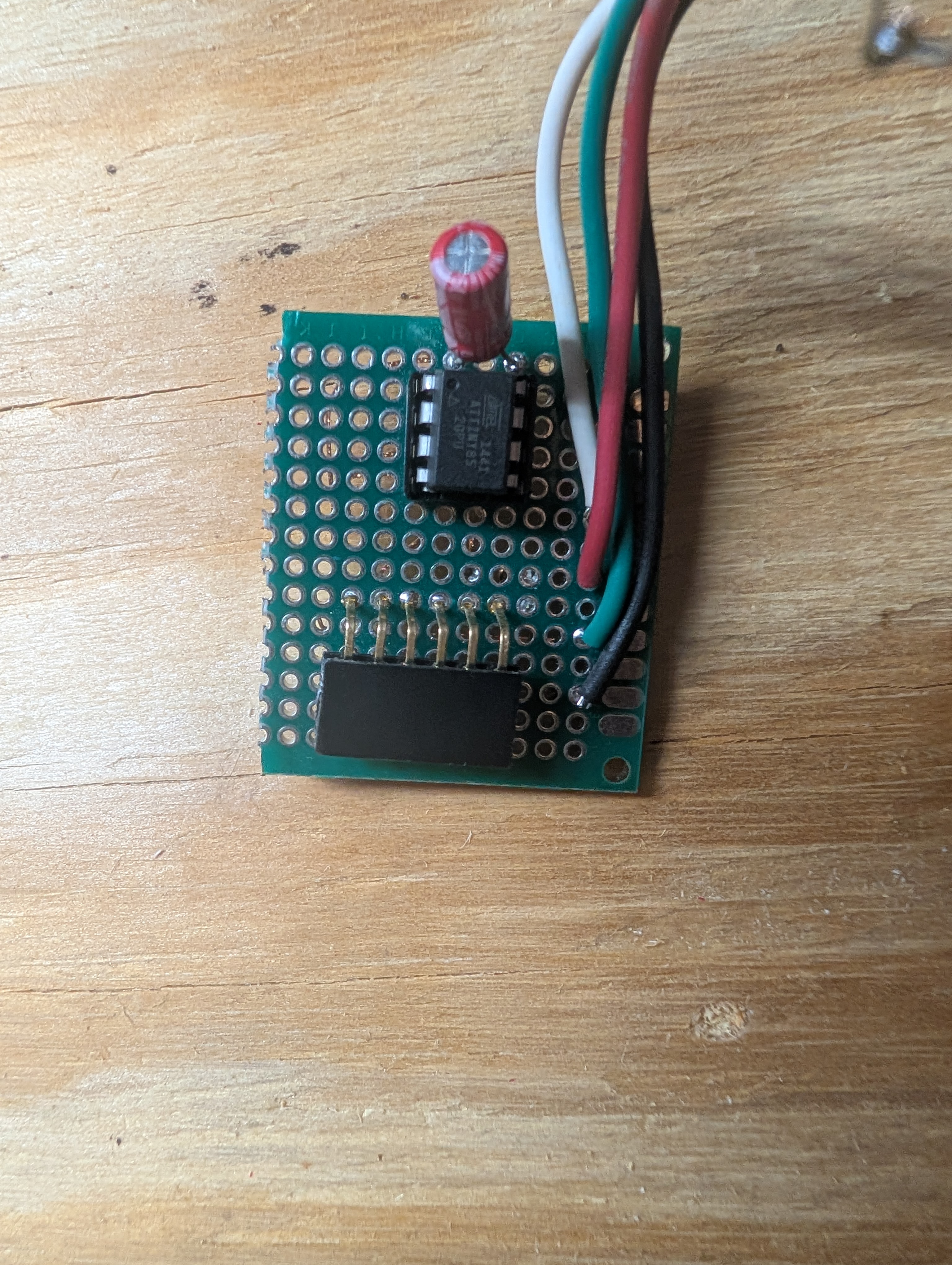
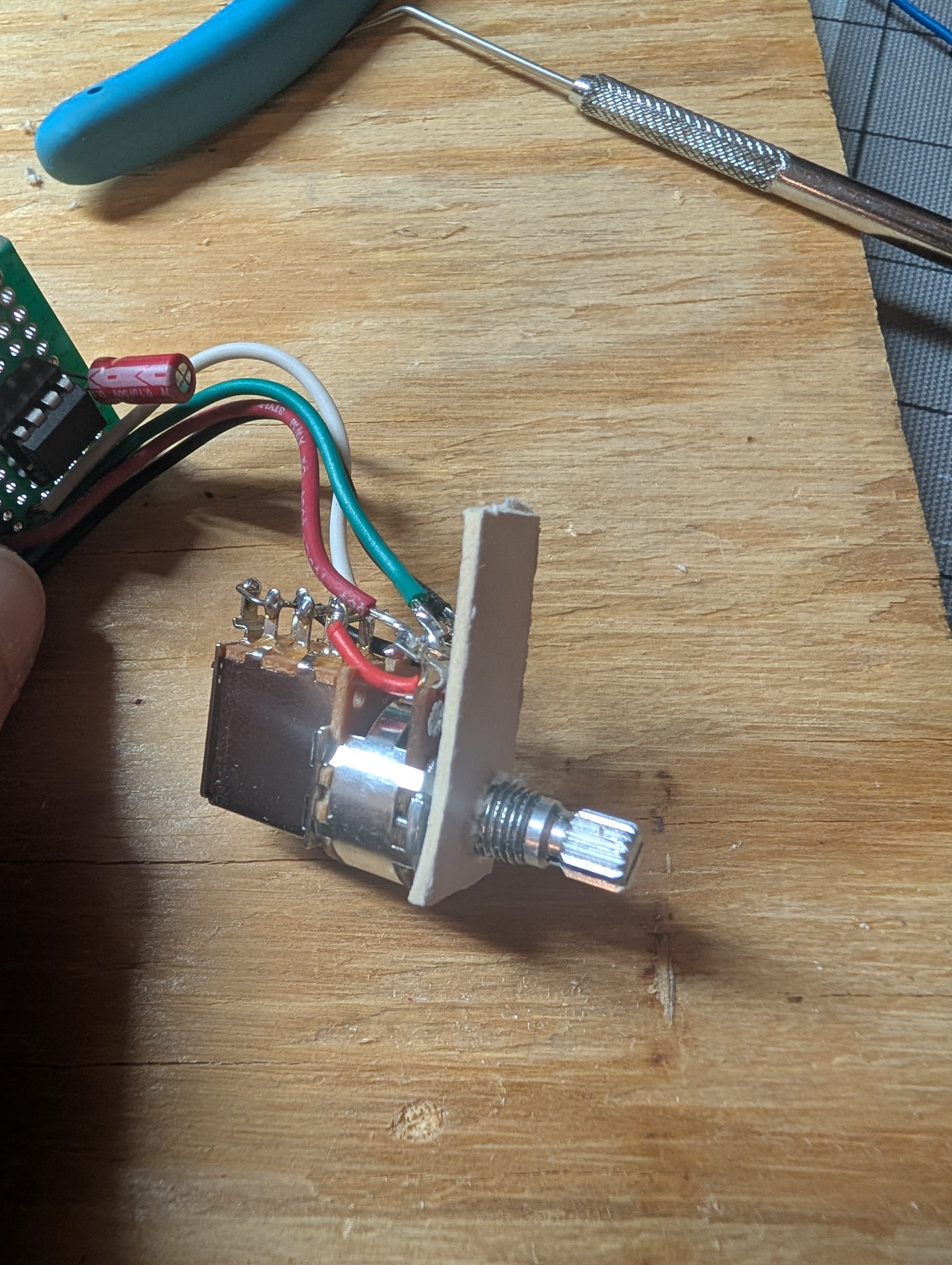
Instead, I decided to emulate the behavior using a pot and microprocessor. An ATTiny85 is an 8-pin DIP mcu that I love for stuff like this. It’s got power, ground, and 6 GPIOs, with an internal RC clock that can run up to 8 MHz. All it needs to do is read the value of a pot through an ADC and write the grey code to the encoder pins. The common pin is connected directly to the 5V power supply which comes from a large LM7805 connected to a heatsink, which means the additional current draw of running a microprocessor should not be an issue. I decided to use a push-pull pot to act as a mute switch, since the amp doesn’t have a standby switch. I prototyped first with an Uno on a breadboard.
Atmel 8-bit ADCs are 10 bits, so converting the the reading to a 4 bit position is a simple bit shift. Unfortunately the only push-pull pots I had on hand were audio-taper, so I need to do a non-linear conversion of ADC value to evenly-spaced 16 positions.
Most audio-taper pots aren’t truly logarithmic, but rather use two piecewise linear approximations.
To build the transfer function, I measured the ADC value at each of the 16 markers on the panel. Then I took the most linear-looking sections of samples and did a least-squares regression fit, generating two linear equations. The inflection point is the intersection of these two lines, which is right around the 9th position (zero-indexed). I used the linear approximations to find “true” values for each of the lines. To avoid slight variations due to noise in causing the amp to switch constantly between states, I added some hysteresis to the bounds by finding the cutoffs 2/3 of the way between each value. That is, in order to step up to the next value you have to turn at least 2/3 of the way there. Then to go back down you have to turn down past 1/3rd. I computed all these bounds using Google Sheets and then added them as lookup tables in the code. I also added an 8-sample averaging low-pass filter to further reduce variance and noise from the ADC. You can see the code below.

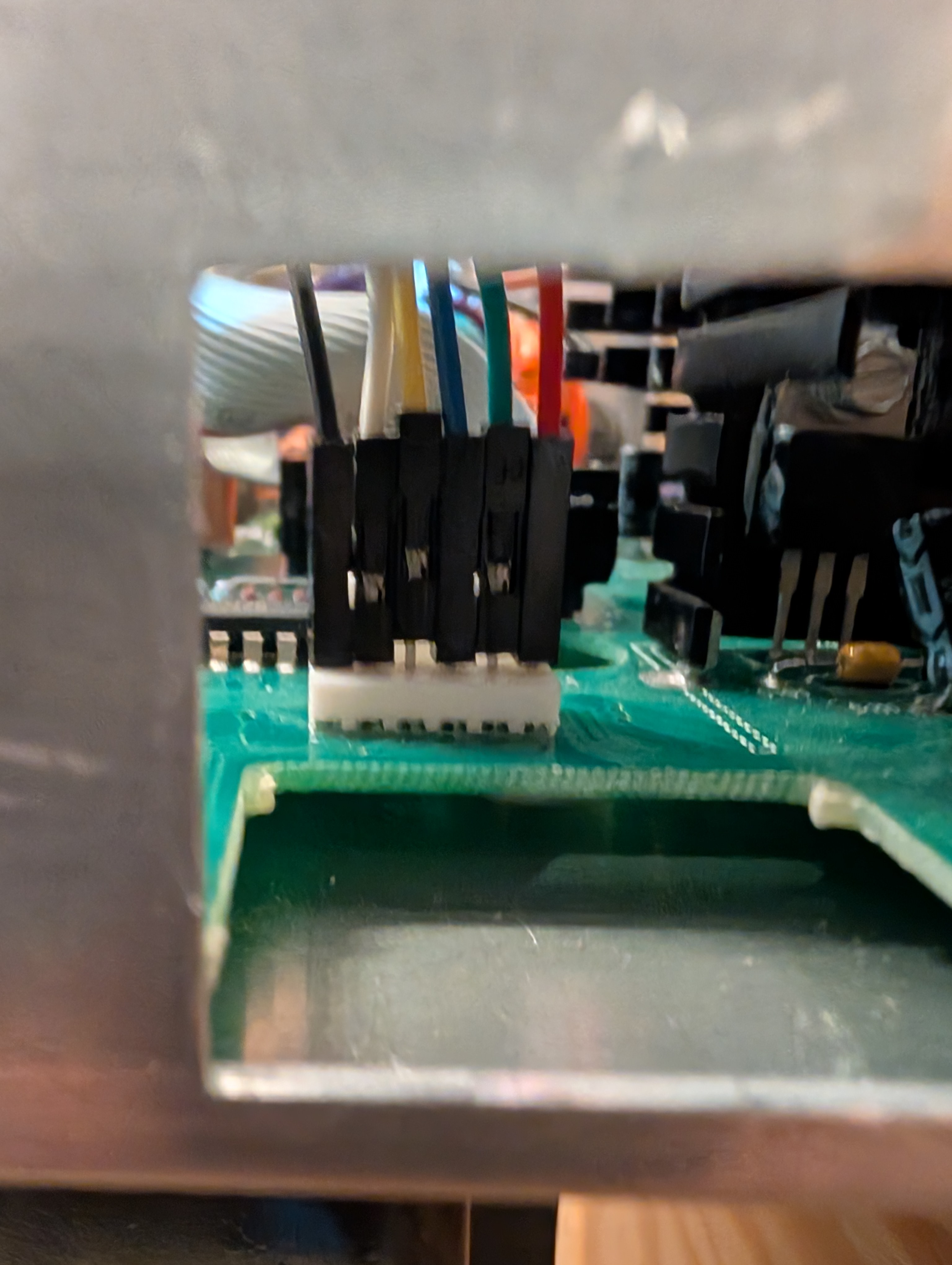
I used a little proto-board to hold the MCU and female headers to plug into the main PCB. The pot had a tendency to short against the metal panel, so I added some electrical tape to the back of the panel, and a little card stock to add some separation. I also went ahead and socketed all the relays and replaced as many as I could. I used the knob from a Big Muff Pi, which matches the aesthetic well.
Now she works nicely. In fact, I consider my mod an upgrade since it adds a mute switch, and the knob has a much nicer feel than the discrete position switch.
Code
uint8_t GRAY_CODE[16] = {
  0b00000000, 0b00000001, 0b00000011, 0b00000010,
  0b00000110, 0b00000111, 0b00000101, 0b00000100,
  0b00001100, 0b00001101, 0b00001111, 0b00001110,
  0b00001010, 0b00001011, 0b00001001, 0b00001000,
};

uint16_t AT_LOWER_BOUNDS[] = {
  0, 6, 25, 45, 64, 83, 102, 121, 140, 162, 227, 367, 508, 648, 789, 929
};
uint16_t AT_UPPER_BOUNDS[] = {
  13, 32, 51, 70, 89, 108, 127, 146, 171, 274, 414, 555, 695, 836, 976, 1024
};

template <size_t LP_SIZE>
class AudioTaperPot {
  uint8_t _pin;
  uint8_t _val;
  uint16_t _samples[LP_SIZE];
  size_t _idx = 0;

  public:

  void begin(uint8_t pin) {
    _pin = pin;
    _val = 0;
    // initialize state
    for (size_t i = 0; i < LP_SIZE; i++) {
      sample();
      delay(10);
    }
  }

  uint16_t sample() {
    // low pass filter
    _samples[_idx] = analogRead(_pin);
    _idx = (_idx + 1) % LP_SIZE;
    uint16_t result = 0;
    for (size_t i = 0; i < LP_SIZE; i++) {
      result += _samples[i];
    }
    return result / LP_SIZE;
  }

  uint8_t measure() {
    uint16_t measure = sample();
    // while (true) {
    if (measure >= AT_UPPER_BOUNDS[_val]) {
      _val++;
    } else if (measure < AT_LOWER_BOUNDS[_val]) {
      _val--;
    // } else {
    //   break;
    }
    // }
    return _val;
  }
};

AudioTaperPot<8> pot;

void setup() {
  pot.begin(A2);
  DDRB |= 0b00001111; // pinMode OUTPUT B0-B3
}

void loop() {
  uint8_t val = pot.measure();
  uint8_t code = GRAY_CODE[val & 0x0F]; // encode via gray code
  PORTB = (PORTB & 0b11110000) | code; // write all 4 bits
  delay(10);
}