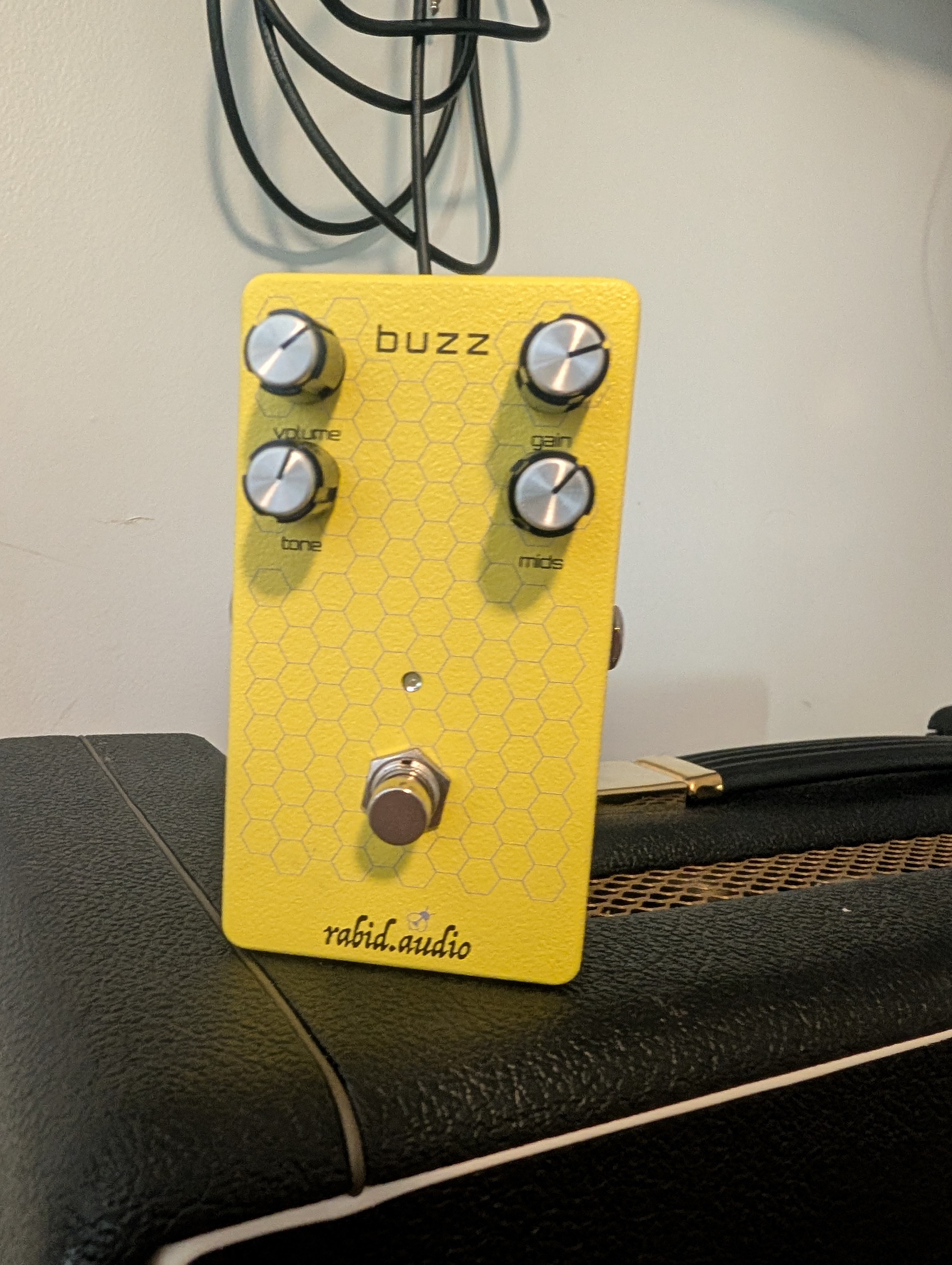
Buzz fuzz pedal
- music tech
- effects pedals
- electronics
Since I first started making effects pedals my interest was always in what I would call “utility pedals” over true effects. My first pedal was a passive fileswitch, inside of a gutted DS-1 case. More recent pedals have been variations on A/B and expression circuits such as the tone splitter pedal from a few years ago (which still needs some revisions). I’m hoping soon to combine all those variations in to one master utility pedal; I have some ideas for it already.
However, this approach has caused me to skip all the interesting classic stompboxes that people usually start with, like fuzz pedals. I decided to turn my attention to fuzz pedals, particularly my favorite, the EH Big Muff Pi. I did actually try to put together a clone early in college (before I’d taken any EE courses or really had any soldering experience at all). I spent hours soldering everything together only for it not to work. I lacked any requisite knowledge to actually diagnose the issue, and was left with a large paperweight. The experience was a bit disheartening, which is probably why I avoided fuzz pedals for so long.
Big Muff Pi
Armed with a degree and 15+ more years of experience, returning to it was much less intimidating. ElectroSmash was very helpful in understanding the circuit. It seems like the site is down now but as of writing it’s still available on the Wayback Machine and I have a PDF copy as well in case it becomes lost media.
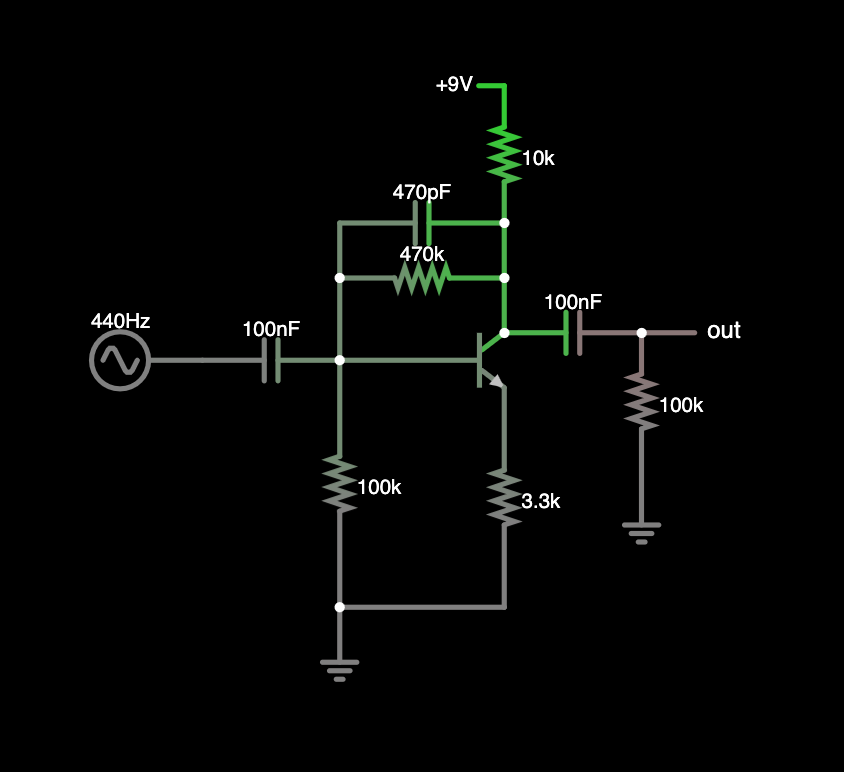
It does a really thorough job of explaining the circuit so I won’t re-post it here, but suffice to say the schematic is really straightforward. It’s 4 common-emitter BJT amplifiers, with a passive tone filter between stages 3 and 4. The final output stage is a textbook CE amplifier, but the earlier stages use a slightly modified topology, with the base pull-up resistor instead feeding back from the output (“Shunt Feedback CE”). This lowers the gain in exchange for better performance in other areas. The small capacitor in parallel improves stability and noise. Then, stages 2 and 3 are identical clipping stages. They are shunt feedback amplifiers with a pair of diodes in the feedback path clipping the signal.
The passive filter is effectively a variable notch filter; with the “Tone” knob in the center, the EQ is mostly flat with a slight mid scoop (giving the circuit it’s distinctive sound). Counter-clockwise it becomes a low-pass, and CW it becomes a high-pass. Other than that there are just some volume knobs on the input and output. The input one, “Sustain”, controls the distortion amount by controlling the level of the signal into the clipping stages, which clip at a fixed voltage. The output “Volume” then compensates for the increased volume do to clipping.
Improvements
There were many variations of the circuit over the years. Typically these were adjustments in transistors or minor component value changes primarily for part availability and cost (though I’m sure you’ll meet people who insist certain circuits sound better than others). You can see the schematics for many variations here. Some of them really piqued my interest though, particularly the “Mayonniase” variant named after the Smashing Pumpkins song (a band for which the Big Muff was a key component of their sound). In this schematic, the tone stack was a bit different, with an additional knob controlling the amount of mid scoop. The Swollen Pickle, also based on the Big Muff Pi, does something similar.
I love the way the classic Big Muff Pi sounds, but I’ve definitely noticed its hard to cut through the mix in a full band setting with a mid scoop. My ideal fuzz would have this same tone but still enough mid range to not get lost.
In order to test and iterate on different fuzz pedal designs, I made a prototyping PCB. Each board allows for one shunt feedback CE amplifier stage, and then each stage can be stacked vertically. This allows testing each stage in isolation, and mixing and matching stages to find desired tones.
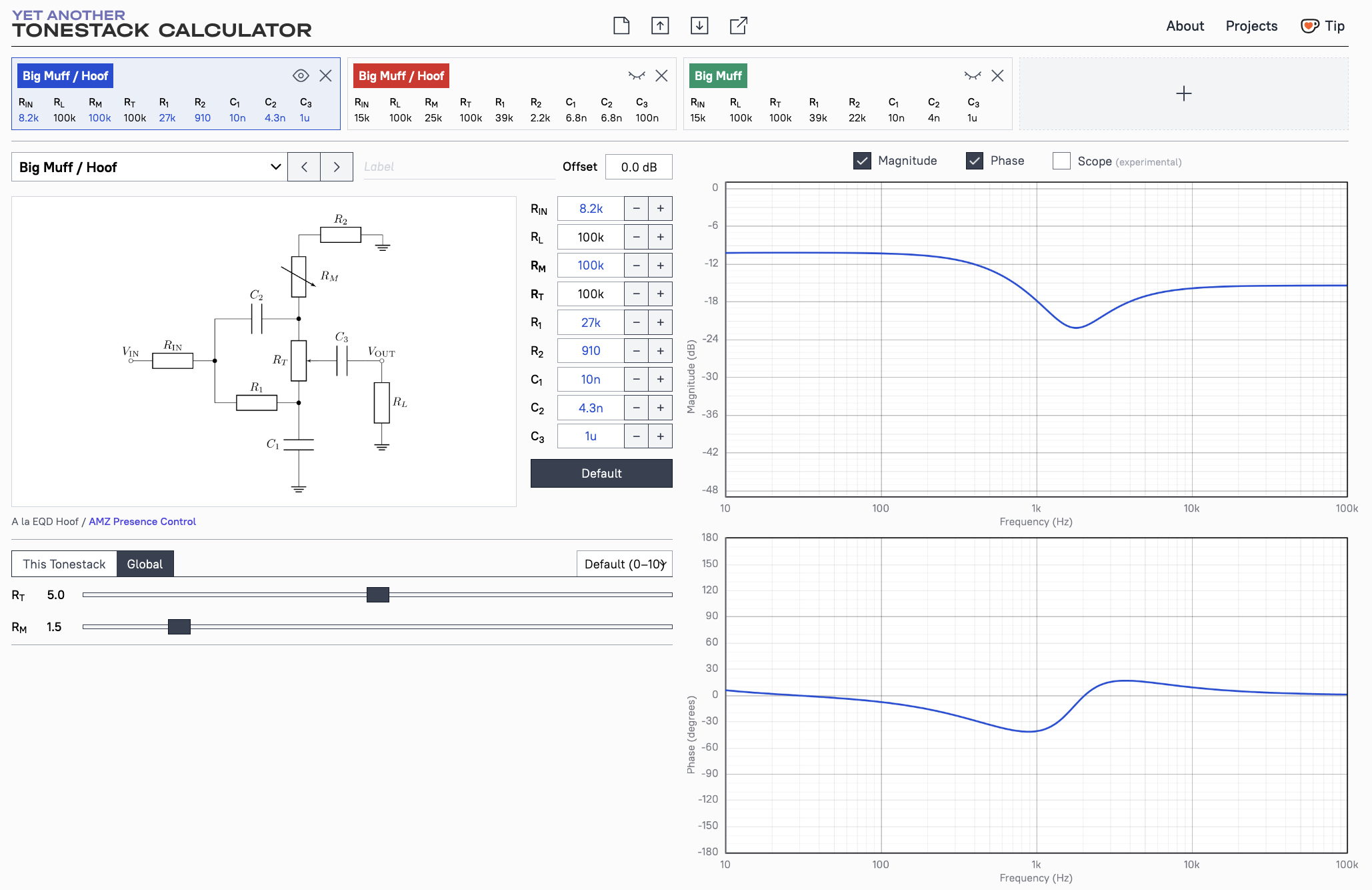
The other tool I relied heavily on is Yet Another Tone Stack which I also used for the JTM45 mods from earlier this year. It has a few variations of Big Muff tone topologies built in, including the one from the Mayo variant. I played with the component values for a while until I settled on this design. The tone range is comparable to the original design with a slightly hotter overall output. The mids control knob has a wide control range, from an extreme mid scoop up to a slight mid boost. At 15kOhms (which is around 50% on a log taper pot), the scoop is comparable to the classic circuit. I also tweaked the other stage component values slightly.
For the PCB I used my normal design approach. I used through-hole components since there’s plenty of room and I figure some hobbyists might be interested in putting together their own. Because stages 2 and 3 are identical, I placed them as mirrors of each other in the center of the board, and slotted stages 1 and 4 on the bottom.
For the case, I used Tayda Electronics’ Drill Service, where they will paint and drill custom stompbox cases at small quantities. I didn’t like any of the royalty-free clipart bees I found online so I drew my own.

It took a couple revisions to work out all the kinks, but I think Rev D is pretty feature complete. The design files are on Github along with assembly instructions if you want to make your own. I also have a few more PCBs, let me know if you’re interested in getting one.
Sample
This is using my Telecaster on the bridge pickup, through my custom JTM-45. Forgive my playing.
- Tone and mids at 50%, gain 25%.
- Tone and mids at 50%, gain 50%.
- Tone and mids at 50%, gain 75%.
- Gain 75%, mids 75%.
- Gain 75%, mids 25%.