Splitter Pedal
Background
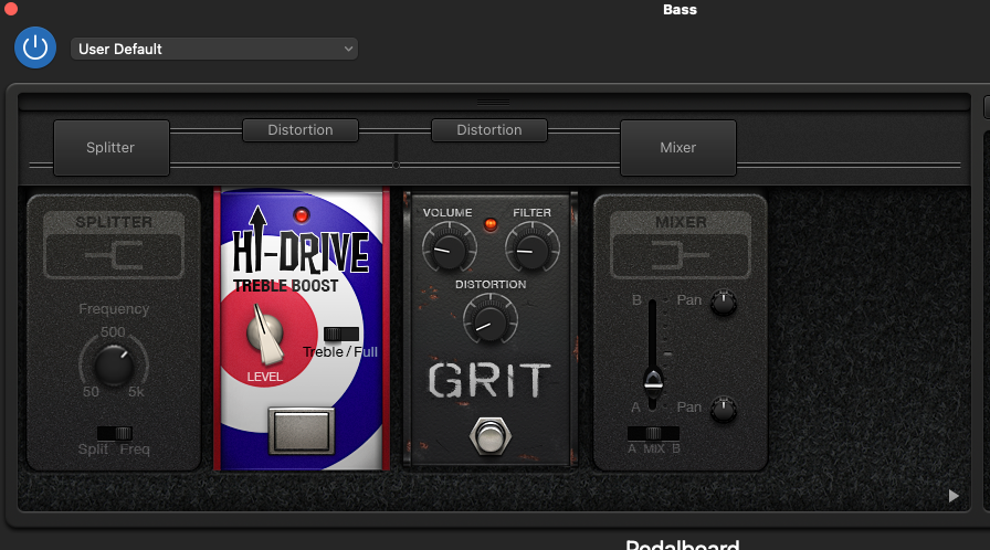
To explain this pedal, I think it’s easiest to start with the problem it addresses. Sometimes you want to apply an effect not to the whole signal but only to one part of the frequency spectrum. A good DAW wil be able to split a signal chain and apply effects separately. One common use of this is in bass guitar, where applying effects like gain to the low end can cause it to sound muddy. Some pedals for bass include a built-in high-pass filter to keep the low-end clean.
Usage
Controls
- Cutoff (45Hz to 20kHz)
- Send mode switch (highs, all, lows)
- Wet/Dry mix
- Bypass switch
This pedal provides the ability to route certain frequencies through a different effects chain and mix back together again. The wet signal is passed through a pair of send/receive jacks, and mixed back with the dry signal to the output.
Bypass
When bypassed (4), IN is connected to OUT (true bypass) and the device is powered off.
Send mode (2) = up (highs)
This mode can be used to apply effects only to the high frequencies while keeping the low frequencies clean. The low frequencies are kept dry while the high frequencies are sent through the effects send/receive. This is particularly useful for bass guitar to keep the low end clear and crisp when applying a fuzz effect for example.
This mode sends the high frequencies from IN to SEND (wet channel) and mixes (3) the RECV with the low frequencies from IN (dry channel). The cutoff controls the frequency separating low and high.
Send mode (2) = down (lows)
Like the up mode but the wet and dry are reversed; the low frequencies are sent through the send/receive and the high frequencies are kept dry. This mode can be used to apply effects only to the low frequencies while keeping the high frequencies clean.
This mode sends the low frequencies from IN to SEND (wet channel) and mixes (3) the RECV with the high frequencies from IN (dry channel). The cutoff controls the frequency separating low and high.
Send mode (2) = center (all)
In the center position mode, the full spectrum is sent down both paths. This mode can be used to turn a separate parallel effects chain on and off, and wet/dry mix the effects signal.
IN is sent to SEND. IN and RECV are mixed (3) and sent to OUT. Cutoff (1) has no effect.
Cutoff
The left knob (1) controls the cutoff point between high and low frequencies, from ~45Hz to ~20kHz. In the center position mode it has no effect.
The right knob (3) allows some blend control between the wet and dry signals. At 12 o’clock, the blend is 50%/50%. Full counter-clockwise is 100% dry and full clockwise is 100% wet.
Source
CAD files, SPICE simulations, and decal designs are on GitHub. Like most everything I do, this is open hardware.

Parts

Passives are 0805 surface mount, and ICs are SOIC.
- 6x 0.1u ceramic capacitors
- 4x 1u ceramic capacitors
- 2x 680p ceramic or mylar capacitors
- 1x 22k resistor
- 4x 220 resistor
- 1x 2.2k resistor
- 3x 10k resistor
- 1x 3mm LED
- 1x TLE2426 virtual ground IC
- 1x TL074 quad op-amp
- 1x LM13700 dual OTA
- 1x Alpha 9mm A1M pot (audio-taper 1M)
- 1x Alpha 9mm B100K pot (linear taper 100K)
- 1x EG2301 DPDT switch
- 1x 3PDT stompbox foot switch [Amazon]
- 1x 2.1mm Barrel jack [Amazon]
- 4x 1/4” jack 6 pin PCB mount [Amazon]
- 1x Case [Amazon]
Assembly instructions
- Solder ICs. Note orientation of pin 1
- Solder resistors, capacitors, and finally TLE2426
- Solder ribbon cable PCB to SW2 and two wires to power supply pins
- Solder jumpers JP1, JP2, and JP3 appropriately. See Jumpers below
- Solder the jacks on the back side of the board. If including optional jacks JACKSEND2 and JACKRECV2, don’t solder those yet
- Place SW1, the pots, and the LED in board but don’t solder them yet. Align the parts with the case. Put the LED through the whole and hold it in place with a bit of electrical tape. Attach the pots and jacks to the case. When everything is aligned properly and flush, solder the LED, pots, and SW1
- Attach DC jack to case and solder power wires
- If including optional jacks JACKSEND2 and JACKRECV2, disconnect board from case, solder remaining jacks, and reassemble
No calibration required.
Design
Power supply
TLE2426 provides a signal ground between 0 and 9V, providing a dual-ended 4.5V power supply for the op-amp from a 9V battery or DC adapter typical for effects pedals.
Input stage
U1A is an input buffer. Since the signal goes directly into the op-amp, this input impedance is quite high (theoretically infinite, in practice upwards of 10MOhm). This makes this pedal suitable as a buffer.
Filter
Two voltage-controlled filters (VCFs), one highpass and one lowpass, with the same cutoff form a crossover filter.
R1/R2/R4/R6/C1/U2A act as a 1st-order active low pass filter with a cutoff which is controlled by the current into pin 16. This topology comes directly from the LM13700 datasheet. Similarly, R3/R5/R7/C2/U2C are a 1st-order active high-pass filter. The filter is identical except for the input is into the capacitor rather than the differential input.
The maximum control current for the LM13700 is 2mA. When RV1 is fully shorted, the total current out of the pot is 4 mA which is then split between the two OTAs.
The formula for the cutoff of both filters is f0 = (R6*gm)/((R4+R6)*2*pi*C1) where gm ~= 19.2*Iabc. Thus, a 680pF capacitor gives a filter cutoff of 20.17KHz at 2mA. As the control current decreases, the cutoff
https://docs.google.com/spreadsheets/d/e/2PACX-1vT8rBejbugFlT3EW5vfu0i-iW_NIMdOeeCCaixy12qmzPs54GQdZPlqS4ZHJ6NFuLR04HVoCBH7RM92/pubhtml
with a Q of 0.5 and a cutoff from 7.2Hz to 7.2kHz. U1D subtracts the high pass signal from the input to get a low pass signal.
To vary both R components of a 2nd order filter, it simply uses a dual audio taper pot. Rather than a true LR active crossover filter, this circuit simply subtracts the original signal from the filtered signal to get the opposite frequencies. This creates a comb filter with an uneven phase shift, which means this pedal will have moderate a tonal effect. Both of these limitations are for cost savings and simplicity. A more robust circuit would use two LR VCFs but this would drastically increase cost and complexity.

Jumpers
From there the signals are routed using the switches and jacks. A complex set of jumpers and test points allow reconfiguring the behavior of the circuit. An additional send + receive pair of jacks for the “dry” signal can be added using JP2/J6/J8, while the behavior of the stereo channel can be changed with JP1/J7 and JP3/J9, for example wiring them to a second PCB for stereo support.
Mixer
Finally U1C/RV2 mixes the wet and dry signals and buffers them to the output. Cost-cutting measures were also used on the mixer design. At this point we’ve used 3 of the op-amps in a quad package. Rather than adding more op-amps to create VCAs, this design simply uses an inverting summing amplifier with a pot to vary the gain of each signal. R7 and R8 are necessary to set a lower-bound on the input impedance. In the center position, each signal sees a gain of ~1 (1MOhm/(470KOhm + 500KOhm)). At the extremes, the lesser signal has a gain of 1MOhm/(470KOhm + 1MOhm) = ~0.68 while the larger signal gets a gain of 1MOhm/470KOhm = ~2.13. This means it’s not linear and will boost one side or the other in extreme settings. It also limits the effective ratio of wet/dry to about 25%-75%, while a more robust circuit would provide a 0%-100% control without any variation in gain.
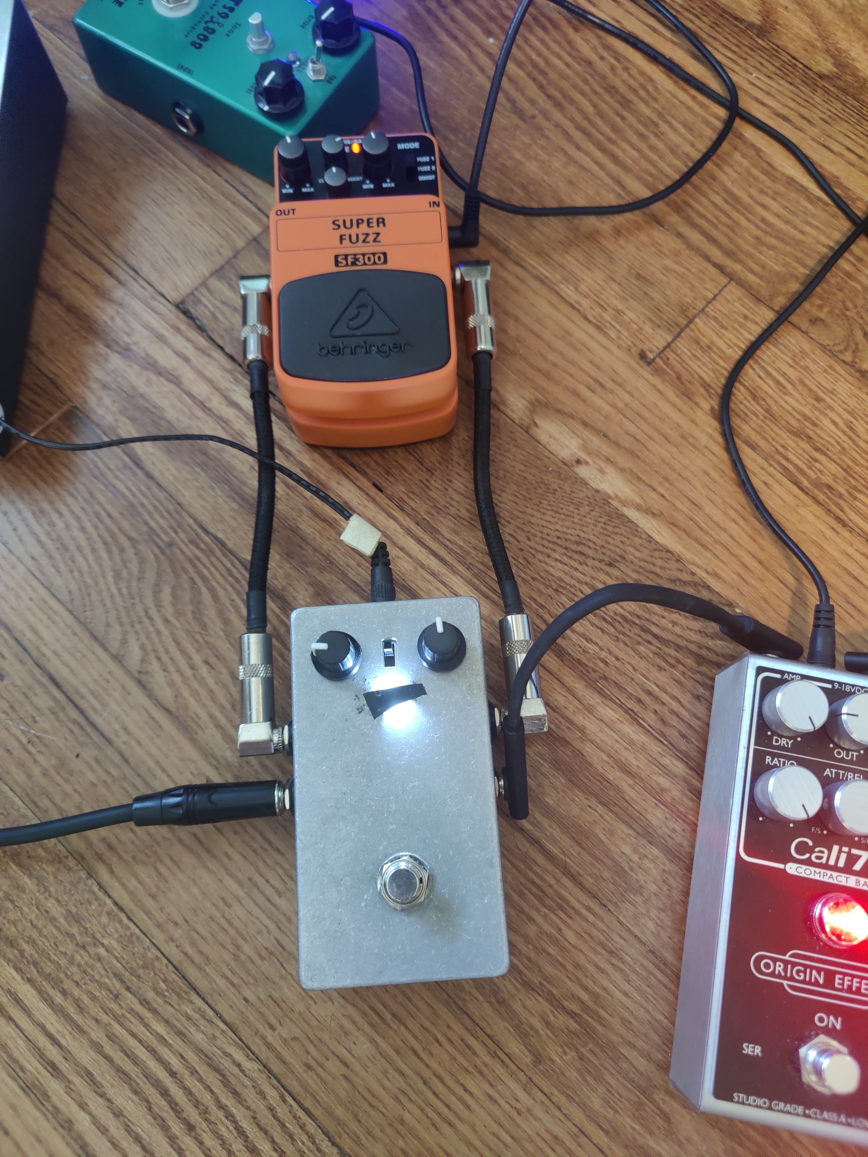
Prototype
Below is a picture of the prototype version I assembled. I only had a white LED on hand, and it ended up being really bright, hence the electrical tape. I also learned the hard way some lessons about fitting components in the case; I had to sand down the jacks to fit, hence why some of them are missing hardware. But it does work. Here’s a sound sample demonstrating applying gain (from the amazing Behringer Super Fuzz) to only the high frequencies.