Synthesizer - The Count
This is a clock Eurorack synth module designed to drive sequencers, drum machines, arpeggiators, etc.
It’s entirely digital, which makes it an easier module to build since most of the complexity is in software.
Source
Source files including code and CAD are available on GitHub. Like most everything I do, this is open hardware.

Status
Complete, Revision B assets are available for download on GitHub. Pictures and assembly directions coming soon. I have a couple of spare panels and PCBs, as well as a few of the specialized parts. If you’re interested in building one I’d be happy to ship them at-cost. Or if you’d be interested in a kit, let me know.
Features
- 15 to 400 BPM
- Tap-tempo input
- CV input for controlling clock speed
- Swing control (a.k.a. shuffle)
- A separate subdivision output which can trigger at an interval relative to the clock speed
- Efficient 3HP size
- Save/load/reset settings
Usage
- 7-segment LEDs display the current BPM. The left LED displays the BEAT output, the right LED displays the DIV output.
- Turn the knob to control the BPM. Base BPM is adjustable from 15-400 beats per minute.
- The BEAT output triggers at the specified BPM.
- The DIV output triggers at a configurable interval relative to the specified BPM.
- Apply a unipolar voltage from 0-5V to the CV input to adjust the clock speed. 0V is no additional increase in rate over the knob setting. Each 1V is 64 additional BPM.
- Tap the knob button two or more times to set the BPM through tap-tempo. This effects the base BPM before the CV is applied.
- Turn the knob while holding the DIV button to control the subdivision setting. The display will show the subdivision value. A division of 1 means that DIV will match the BPM. At 2, DIV will trigger twice for each beat. At 1/2, DIV will trigger once every 2 beats. Allowed values: 1/8, 1/7, 1/6, 1/5, 1/4, 1/3, 1/2, 1, 2, 3, 4.
- Turn the knob while holding the SWING button to control the amount of swing from -75% to 75%, adjustable in steps of 3%. Swing applies an offset ot every other beat. LEDs display the swing amount. Negative values lag while positive values lead. 0% is played straight, and 66% is exactly a triplet feel.
- Press both the DIV and SWING buttons at the same time to pause the output. While paused, LEDs display
||. - While paused, tapping the knob button will manually trigger one beat. This can be useful for synchronizing the module with a sequencer.
- While paused, holding buttons will manipulate the saved settings. Hold the DIV button for 2 seconds to save the current settings (BPM, subdivision, and swing). The display will blink
SSS. These settings will be loaded whenever the module is powered on. Hold the SWING button for 2 seconds to load the saved settings. The display will blinkLLL. Hold the knob button for 2 seconds to perform a factory reset, returning the saved and current BPM, subdivision, and swing settings to the factory defaults. The display will blinkFFF. - Un-pause the output by pressing DIV and SWING at the same time again.
Assembly Instructions
BOM
There’s a small number of components necessary here, and most are generic. Passive components do not require
high tolerances; 20% resistors will work just fine. Here I used a 1N4148 diode, but any general-purpose diode
should be fine (1N4001, etc). The firmware will run on a ATmega168P but you can also use a higher-memory version
such as the more-common ATmega328P used by Arduino. Unfortunately, it’s really hard to find 7-segment displays
in a 10mm wide form factor. I settled on the SM460281N which can be shipped from
China from LCSC.
The jacks are standard Thonkiconn 3.5mm which you can get from [ThonkDIY] (and probably other places too?).
| Resistors | ||
|---|---|---|
| 1x | 180K | R1 |
| 1x | 100K | R2 |
| 5x | 1K | R3, R4, R5, R9, R10 |
| 6x | 10K | R6, R7, R8, R11, R12, R13 |
| Capacitors | ||
| 1x | 10u electrolytic | C1 |
| 3x | 10n | C2, C5, C6 |
| 2x | 22p | C3, C4 |
| Diodes | ||
| 2x | 3mm LED | D1, D2 |
| 1x | 1N4148 (or similar) | D3 |
| Everything else | ||
| 1x | ATMega168P | U1 |
| 1x | LM7805 5V regulator | U2 |
| 3x | SM460281N 10mm 7-segment display | U3, U4, U5 |
| 1x | 16MHz crystal oscillator | Y1 |
| 1x | PEC11R Rotary encoder | RE1 |
| 2x | TL1105SP pushbutton switches | SW1, SW2 |
| 1x | 2x3 2.5mm male pin headers | J1 |
| 1x | 2x5 2.5mm male pin headers | J2 |
| 3x | 1x5 2.5mm female pin headers | J3, J5, J7 |
| 3x | 1x5 2.5mm male pin headers | J4, J6, J8 |
| 1x | 1x7 2.5mm female pin headers | J9 |
| 1x | 1x7 2.5mm male pin headers | J10 |
| 3x | Thonkiconn 3.5mm jacks | J11, J12, J13 |
Purchase
- SM460281N 10mm 7-segment display: LCSC
- Thonkiconn 3.5mm jacks: Thonk
- Everything else (except passives and pin headers) Digikey
Steps
- Start by soldering the resistors to both boards. Note that they go on both sides of the top board: Top board, top face: R9, R10, R13 Top board, bottom face: R1, R2, R7, R8, R11, R12 Bottom board, bottom face: R3, R4, R5, R6
Clip the legs close
-
Capacitors Top board, top face: C6 Top board, bottom face: C5 Bottom board, bottom face: Orientation
-
Diode top board, bottom face orientation
-
Crystal oscillator, bottom board bottom face
- ISR and eurorack headers
- LM7805, bottom board, bottom face
- IC holder
- Female headers bottom board + Male headers, top board sandwich together and solder
Take a break
insert components, but dont solder yet switches, with caps rotary encoder. electrical tape on bottom. put nut ~50% of the way down LEDs - long legs positive (jack side) Jacks 7 segment displays (period down, rotary encoder side) put panel on - nuts for jack and rotary encoder. adjust lower rotary encoder jack for level panel height Solder jacks, encoder, and switches (NOT LEDs yet) Push LEDs into position in panel. can use tape. may have to angle/bend LEDs.Solder. Push up 7-segments. legs probably too short for flush with panel. use tape to
Programming firmware
You’ll need a programmer in order to load the firmware onto the chip. The simplest way to do this is to use an Arduino Uno and swap the chip into the 28-pin header. You can also use a programmer with the standard ISP header pinout such as the USBtinyISP, USBasp, Atmel-ICE, etc. to program the chip directly onto the assembled board.
If you’ve got a brand new bare chip, you’ll need to start by setting the clock fuse byte. You’ll need to be sure to set the clock to an external 16MHz clock or else the display will blink annoyingly and the beat output will be too slow. You can do this using the Arduino IDE or using avrdude directly:
# NOTE: you'll likely need to tweak this command for your programmer, and for the chip if you're using a 328p instead
avrdude -c usbasp -p m168p -U lfuse:w:0xFF:m
After that, you can program the chip using PlatformIO:
platformio run -t upload --verbose
No calibration is required.
Reduce brightness of LEDs by increasing the value of R9 and R10
Design
View online
The ATMega328P is used as the core microprocessor. Originally I planned on using the ATTiny85 with an HT16K33 LED driver, but there were just enough available pins on the Mega to drive the 7-segment displays directly, and the availability of a 16-bit timer drastically improves the resolution of the clock.
An ISP header allows reprogramming of the firmware using any AVR programmer.
The code uses PlatformIO for build tooling. Separate C++ classes encapsulate logic of each of the components, using header-only files to simplify file structure.
This is a relatively simple module, all digital module with most of the logic in code. However much of the complexity comes from targeting a 3HP size. 1HP is only 5.08mm wide, so we’re working with effectively 15mm of horizontal space. Some weird schematic wiring and pin assignments is done to simplify PCB routes.
Timer
Timer1 is a 16-bit timer which is used as the clock core. This way the main loop is free to focus on user input without worrying about timing or performance; Timer1 will interrupt when it’s time to trigger a clock signal. It counts from 0 up to the value in register OCR1A, at which point an interrupt is issued and the timer restarts. We bring the clock pin high when the timer is at 0. We use OCR1B as a second interrupt at 313 to bring the clock signal low again, creating a fixed pulse width of 16ms (chosen such that at the highest timer frequency the duty cycle will be about 50%).
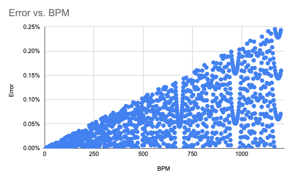
The formula for timer frequency is 16_000_000/((OCR1A+1)*1024) where 16_000_000 represents the the 16MHz system clock of the ATMega and 1024 is the pre-scaler setting For a 16-bit timer this gives a possible frequency range from 5208 Hz to 0.238Hz. See the datasheet for a more thorough explanation of AVR timers.
Rather than doing this heavy floating-point math on-device, these were pre-generated and loaded into flash as a lookup table.
The timer has a maximum error of 0.03% for pulses less than 5 Hz (300 BPM) and less than 0.13% for the maximum pulse rate of 26.6 Hz.
Subdivisions
A song in 4/4 time at 120 BPM will have 120 quarter notes every minute. But most music further subdivides the beat into smaller intervals. Most sequencers will be set up to play a 16th note per step for example. This module assumes this situation by setting the default subdivision value to 4. That means that for every beat, the DIV output will trigger 4 times. If BEAT triggers quarter notes, then DIV triggers 16th notes. Setting the subdivision to 1 causes BEAT and DIV to be the same.
Fractional subdivisions, or super-divisions, are also allowed. In this mode, DIV will trigger an integer multiple of beats. So if BEAT represents a quarter note, a subdivision of 1/2 will cause DIV to trigger on half-notes and 1/4 on whole notes.
The way this is accomplished is by checking which of BEAT or DIV will be higher frequency, and setting the timer internally to use that clock speed. It then counts the number of clock signals and triggers the lower frequency output at an integer multiple of the timer. Thus, while the maximum base BPM is 400, a subdivision of 4 will have a BPM of 1600, or about 27 Hz.
Swing
Swing works by alternating each beat between two different timer values. These timer values average to the base clock frequency, but their ratio is controlled by the swing value. At 0, the beats are even and there is no swing. At 66% the swing beats are triplets. The module allows going up to 75%, which is a quarter adjustment. In most musical styles that use a swing feel, such as jazz, 50%-66% is a common range.
The way this is accomplished is by calculating an offset from a straight interval. For example, with a BPM of 120, the timer will count to 7812. A triplet of 7812 would therefore have a counter value of 7812/3 = 2604. Rather than triggering after exactly 7812, we can instead alternate triggering on 7812 - 2604 = 5208 and 7812 + 2604 = 10416, swapping OCR1A between these two values after every trigger.
This feature is designed to be used with subdivisions, as it adjusts the core timer interval, and therefore causes the output with the higher frequency to swing. If a fractional subdivision is used, the BEAT output will be swung, which may not be the desired behavior.
LEDs
Most 7 segment displays are quite large, too large for our 3HP form factor. However I was able to find some 10mm wide 7-segment displays from China. One quirk is despite clearly having a decimal LED, there’s no pin exposed for it; just the 7 main segments and the common cathode.
Rather than drive all 7*3 = 21 LEDs at the same time, the microprocessor steps through each display one at a time and sets the character for that display. Not only does this reduce the number of pins required (to 7 + number_of_displays), it also uses less power.
The common cathode for the selected display is pulled low, while the common cathode for the other displays remain high. The microprocessor round-robins through each display approximately every 1ms, which is fast enough that our eyes perceive this as a reduction in brightness rather than a blink. With three displays, each display is on 1/3 of the time, cutting the brightness to 33.3%. At higher numbers of displays this solution would start to break down as the brightness would become too low, but for this application it works quite well.
To display a character, each of the 7 segments is controlled by one pin. To optimize performance, all 7 displays are put on the same PORT (in this case PORTF) allowing them to be controlled via a single register and therefore set in a single instruction. Every supported character has a 7-bit bit mask that indicates which segments are on or off. For example:
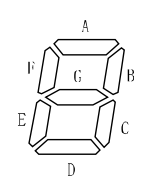
                   //_ABCDEGF
#define EIGHT      0b01111111 // all the segments on
#define SPACE      0b00000000 // all the segments off
#define ONE        0b00110000
#define UNDERSCORE 0b00001000

void write(uint8_t bitmask)
{
  // We're only using 7 LS bits for controlling
  // the display, the last bit may be used as another
  // IO, so we don't want to overwrite it.
  *_segmentPort = (bitmask & 0b01111111) | (*_segmentPort & 0b10000000);
}
Knob
Rather than a potentiometer, the knob control is a 24-detent rotary encoder. Pin-control interrupts (PCINT) detect rotations and keep track of the number of steps. Then the main logic loop polls this and adjusts the parameter as necessary. This video is pretty good at explaining how a rotary encoder works.
Power supply
While the Eurorack power connector has a 5V power supply line, in this module I’m using the 12V supply line and an L7805 to regulate the 12V line to 5V. The reason for this is the high current requirements of the display. Most Eurorack power supplies have a lot more current available on the +12V line than on the 5V and -12V lines.
These LEDs have a forward voltage drop of ~2V. With a 1Kohm current limiting resistor, that means each LED is driven with (5V-2V)/1Kohm = 3mA. There are two additional LEDs that blink with the outputs. That means even with only one display on at a time the LEDs alone require up to 9 * 3mA = 27mA at any given time, and that’s before factoring in the microprocessor, which is another 10-15mA.
CV input
This is a digital circuit operating at 5V, but in Eurorack world CV lines are often -10V to 10V. We need to protect our precious microprocessor against a user mistakenly applying a high (or low) voltage to the CV input.
For more precision we could use an op-amp, but here the requirements are minimal and the space is tight, so I opted for a much simpler solution: a diode and voltage divider (D3, R14, R15). The diode protects from negative CV inputs by ensuring the CV is always forward biased. The CV input is unipolar, but if you apply a bipolar CV, the negative components will be treated as 0, no change in tempo. This does effect the bounds slightly, as to overcome the diode, the CV needs to be at least ~1V. However, you can easily tune the base BPM or CV input to account for this.
To protect against voltages of greater than 5V, a simple voltage divider is used. The voltage is scaled by 100Kohm/(100Kohm + 180Kohm) = ~36%. Thus if you apply the +12V rail to the CV in (the hypothetical highest voltage available in a Eurorack system), the microprocessor’s analog input will see 4.39V, comfortably below the 5V supply range.
Front Panel
In the past I had planned on using toner transfer to apply decals to hand-cut aluminum sheets, but this is a huge pain. It turns out a much more popular approach in DIY synth is to use a PCB as a panel. Then you can design it the same way as the PCBs, send it off with the boards to be manufactured together, and you get some neat color options. JLCPCB also offers 1-sided aluminum PCBs which are perfect for this, as you still get the strength and appearance of using aluminum. Here I printed black silkscreen on white boards. Then anywhere with soldermask reveals the silver-colored aluminum underneath.
I was struggling to come up with a good panel design, so I reached out to the Mastodon synthdiy community. Olksiy H helped me think through a theme and designed a sick front panel. I later went back and tried my hand again using the techniques I gathered from him. Both variants are available in the source code.
Fix in a future iteration
As this is my first fully-complete module, I learned a lot. There’s some things I’d do differently that I may fix in a future revision, but weren’t worth fixing at this time.
- Add standoffs to hold the two boards together. Relying on pin-header friction is not the best
- Rethink components beneath rotary encoder. Too easy to short out
- Make the front panel symmetrical
- More intuitive keyboard shortcuts
- CV in isn’t all that valuable; another output (or an external clock input) would be more useful
- Reduce brightness of LEDs by increasing R9 and R10
- More space around programmer so it’s not running into regulator