CV-MIDI clock converter
In addition to my other NiftyKeyz mod from this weekend, I also modded the clock behavior.
My new clock module works great. It’s designed to be the source clock for the whole rack. However, the NiftyKeyz has it’s own internal clock, which it uses for the arpeggiator and for it’s clock output CV. There’s no external clock input jack, but there is the ability for it to take in an external clock over MIDI.
So I used a Teensy 2.0 to take in clock signals from a CV input and output MIDI clock messages.
MIDI clocks
Unfortunately it seems the MIDI org has put a lot of the spec behind a login page, and the clock function doesn’t seem to be all that well documented. Fortunately it’s pretty simple and I was able to figure it out with a little Googling and some trial-and-error.
Unlike other messages such as note-on/note-off, these are global messages that aren’t sent
to a specific channel but instead broadcast to the whole chain. The clock source sends a start
message 0xFA, followed by a series of clock messages 0xF8, 24 per beat. It can be stopped with
a stop message 0xFC.
The choice of 24 clocks per beat is curious. This is likely to make it easier to support 3/4 and 6/8 time signatures, but it’s pretty annoying from a microprocessor perspective to have a prime factor of 3 in the math.
Implementation
While I could have used just about any microprocessor, I used the Teensy because it’s got native USB including MIDI-over-USB, which was useful for testing, and the ATmega32U4 includes 2x 16-bit timers, which ended up being central to the solution.
I wanted to be able to send in the base beat clock and have the module sub-divide it into 24 clocks. First, Timer1 is configured to run in normal mode, where it just counts up to 65535 and triggers an interrupt when it overflows. If I set the timer counter to zero on the first clock, I can very accurately measure the time between internal beats by checking the counter value on the next pulse.
I wanted to support as close a range to my clock module as possible. After some math, a prescaler of 1024 on a clock speed of 4MHz allows the input clock as low as ~3.5 BPM before the timer overflows. At a 1600 BPM, the counter value would be 145, which is still a reasonable resolution.
So with Timer1 we are able to measure the input clock speed. Then, we can set Timer3 in CTC mode to trigger at that rate / 24. When it’s interrupt triggers, we output a MIDI clock message. A prescaler value of 64 gives counter values from 96 to 41665 over the same range (1600 to 3.75 input BPM, or MIDI clock messages at 640Hz to 1.5Hz).
In order to convert the counter values of Timer1 to the counter values of Timer3, we have to take these prescaler values into account.
T3 = T1 * (1024 / 64) / 24
T3 = T1 / 1.5
Again unfortunately since there’s a factor of 3 in here, we do have to do floating point math in order to calculate this. Fortunately I measured the time of this computation on 16-bit unsigned integers to be around 16us on the ATmega32U4 at 4MHz.
Logic
The code works mostly from within interrupts:
- Clock input rising edge interrupt:
- First time:
- Reset and start Timer1
- Subsequent time:
- Check Timer1 counter value
- Set Timer3 to Timer1 / 24
- Reset both timers
- First time:
- Timer3 interrupt:
- Trigger MIDI clock message
- Timer1 overflow:
- Turn off timers, as it seems the clock inputs have stopped
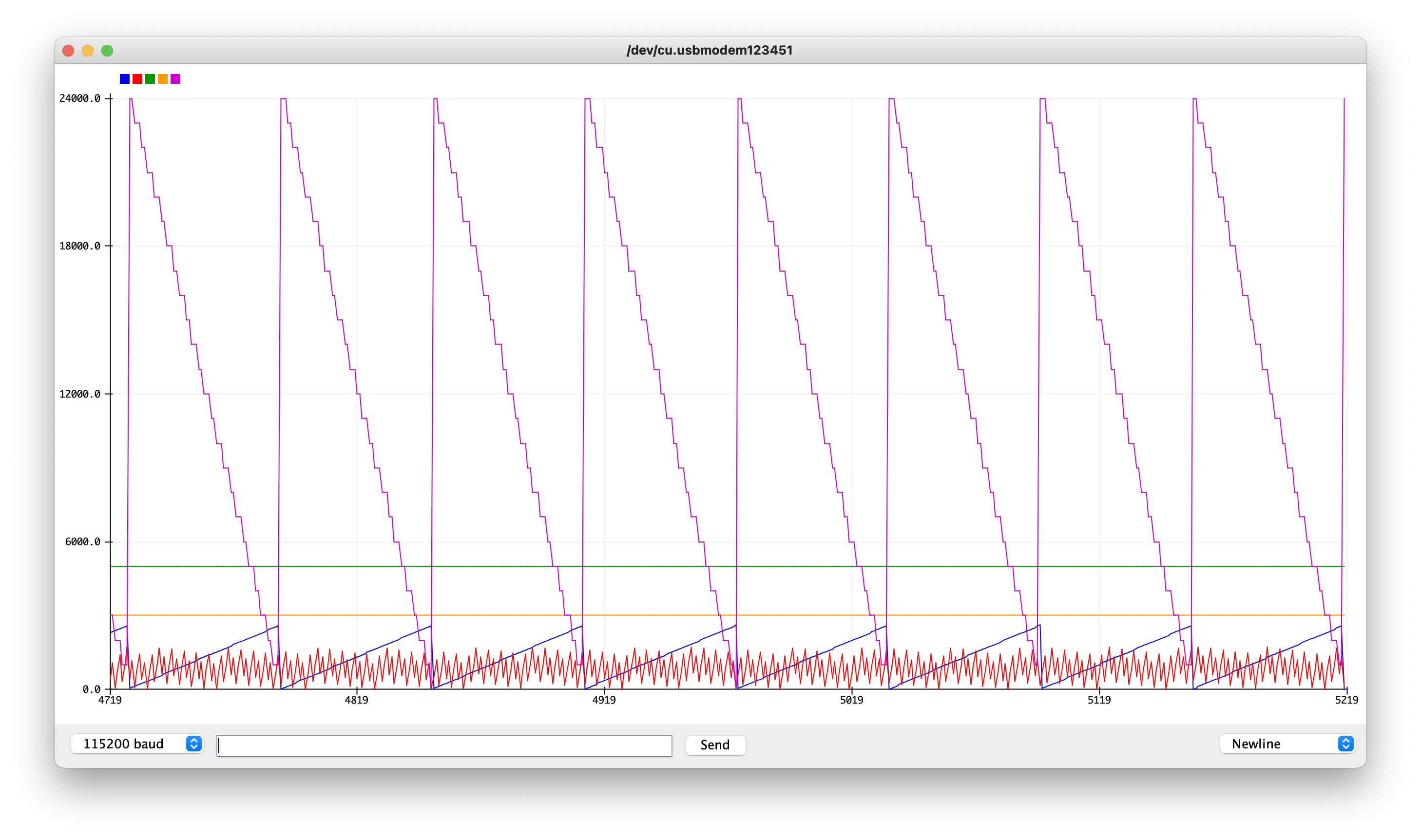
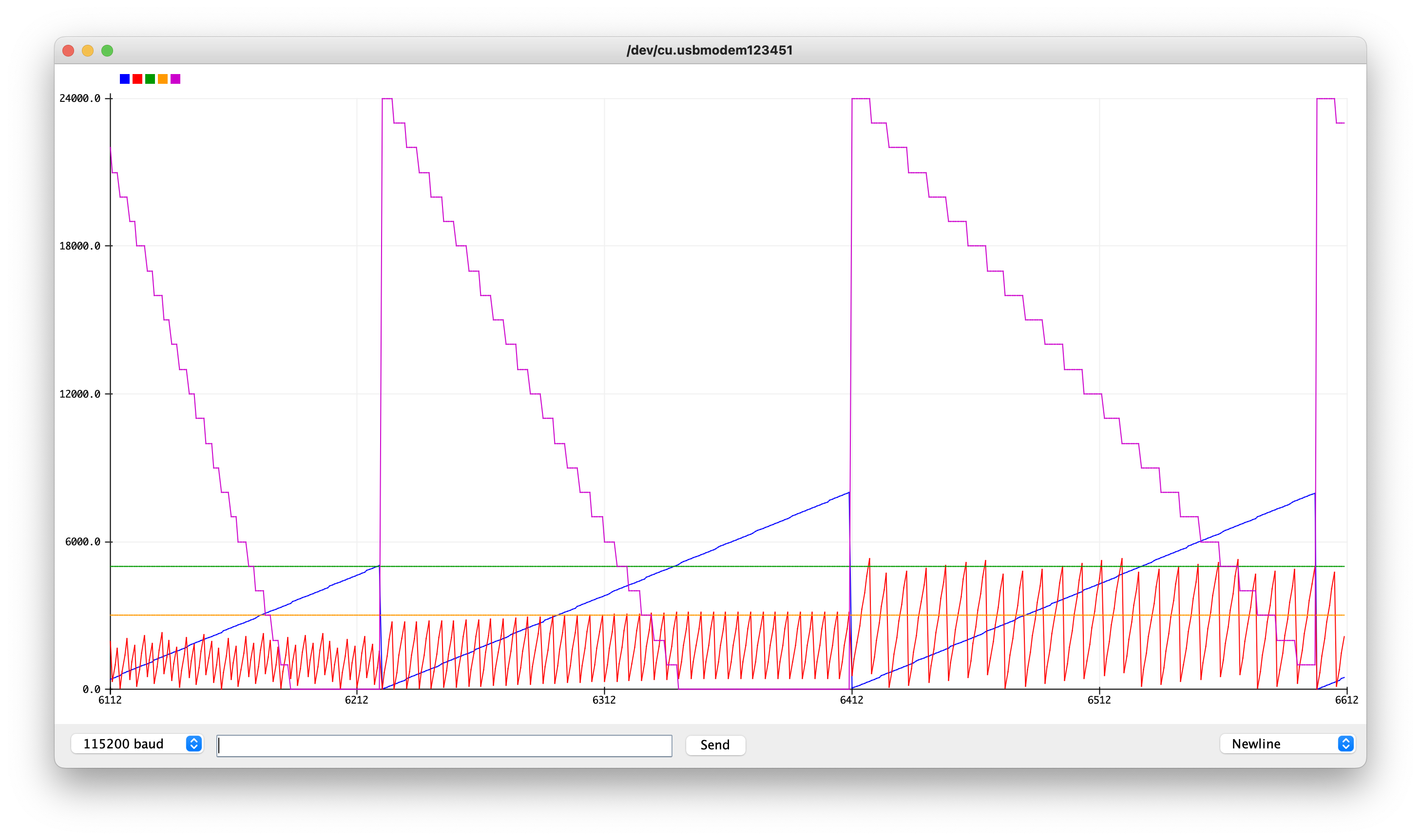
This debugging chart shows the typical behavior. Here, the red signal is Timer3, the blue is Timer1, and the purple represents the number of MIDI clock messages left. Timer3 is often aliased due to undersampling, but at slower rates you can see that it does indeed trigger 24 times for each blue line.
All of this works if the input clock is stable. However, we also need to account for input clocks that get faster or slower. If getting slower, all we have to do is send only the first 24 clocks of the beat. When the next input clock eventually comes in, the new clocks will start at the updated tempo.
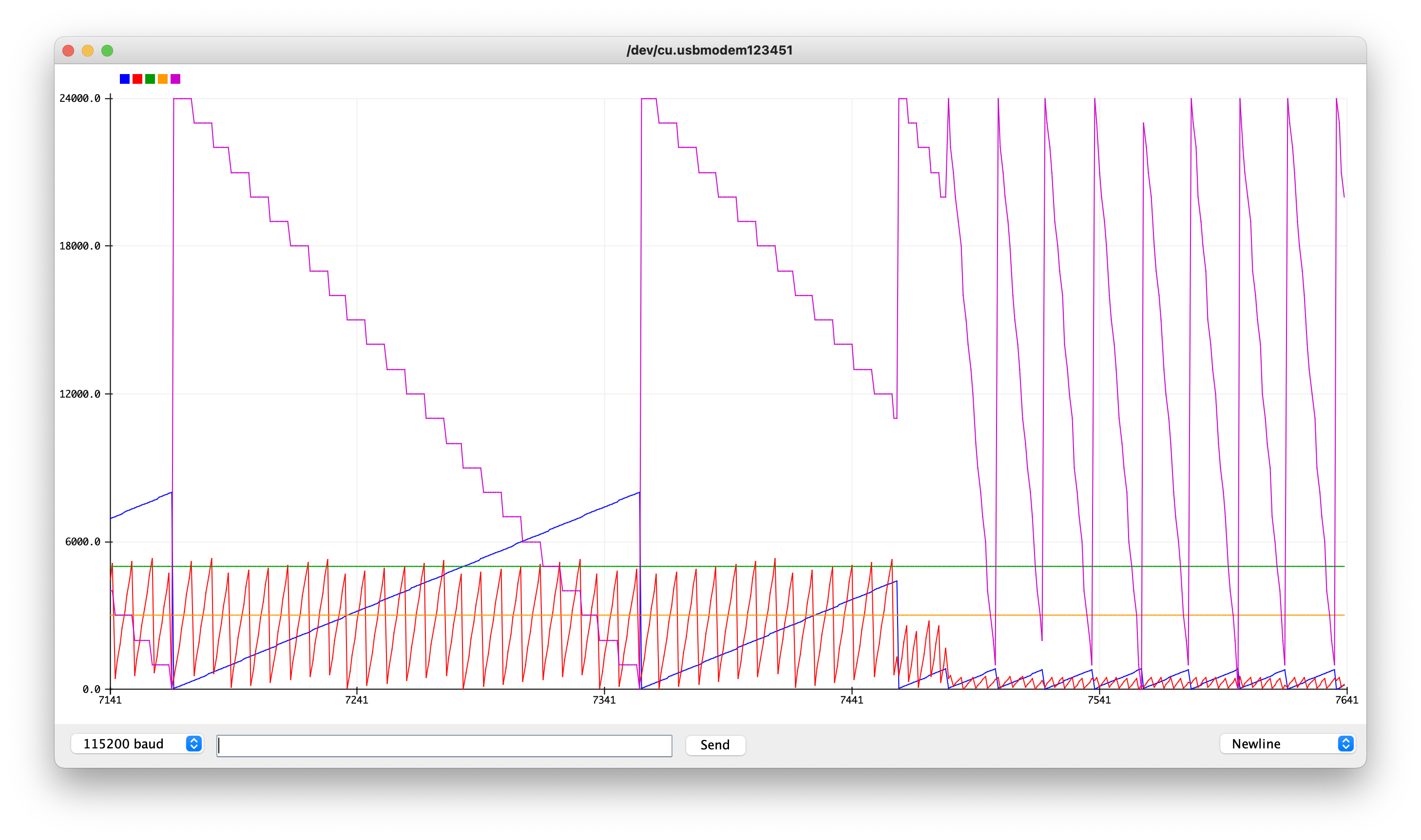
If the input clock is getting faster, the best solution I could find is to quickly beat any of the remaining 24 beats and then start at the new rate.
You can see the well-commented source code here. Eventually I’d like to make a helper library for generating these timer registers. In the meantime I simply commented the configuration of the registers.
Finally, I added a button to start and stop the signal. I left room for a MIDI-in jack to pass through any signals along to the keyboard, but I didn’t solder it yet.
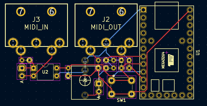
I may eventually run a board of this and hack on the keyboard to put it in the case itself. In the meantime though I just made a protoboard version and taped it to the back.
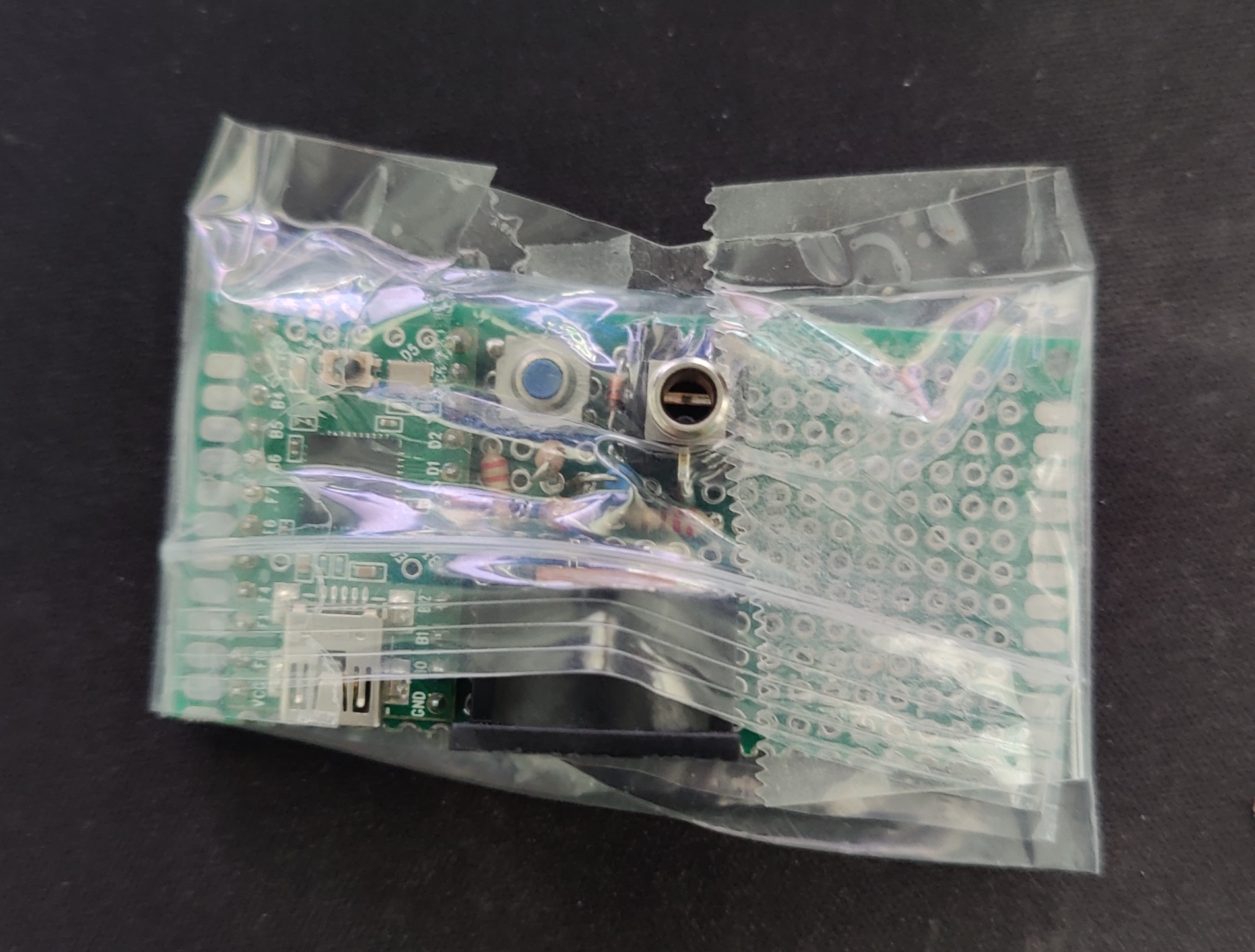
As usual, source code and schematics on GitHub!