Partscaster Build Part II - Prototyping
- music tech
In this post I’ll cover most of the work on the guitar I planned in the last post. This time I remembered to take a lot of progress photos. Let’s get into it!
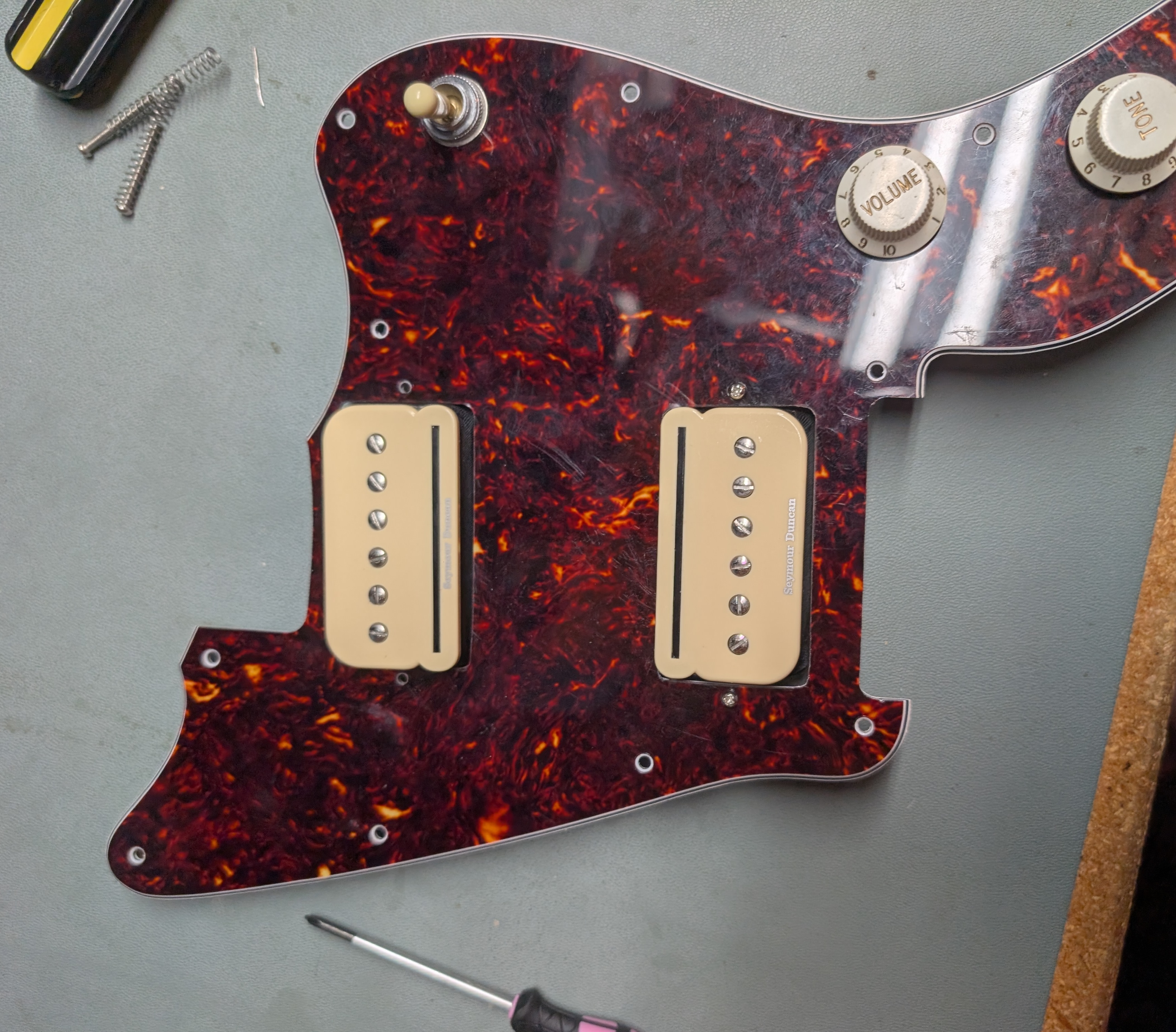
Pickguard
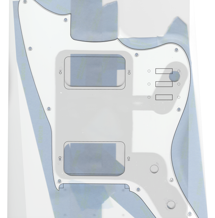
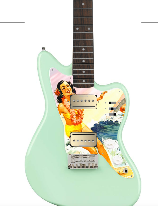
The plan for the pickguard is to cut a custom one from clear PET, and apply a custom decal on the backside so it shows through the clear material, protecting it from damage. I have to cut a custom one anyway for the hardware changes I plan to make.
I started by scanning all the parts I was using with a basic desktop printer/scanner. I loaded these as separate locked layers in Inkscape and reduced their opacity so I could see a guide while working. The official Jazzmaster dimension file I found didn’t help much; the Squier Mini isn’t just a scale-down of the original but a unique design. I ended up tracing the outline in Inkscape. I went ahead and added a bunch of other layers so I could get a sense of the final product.
Cutting went pretty smoothly. Since I’d never cut PET with the laser cutter before, I started by using a scrap piece to test out a couple different cutting settings. After some trial and error, I found three passes at a fast speed to work very well. The protective covering would get a little burned on the edges, but the actual material edge was very clean, and melted in a way that wasn’t super visible but added a smoothness and security to the edge.
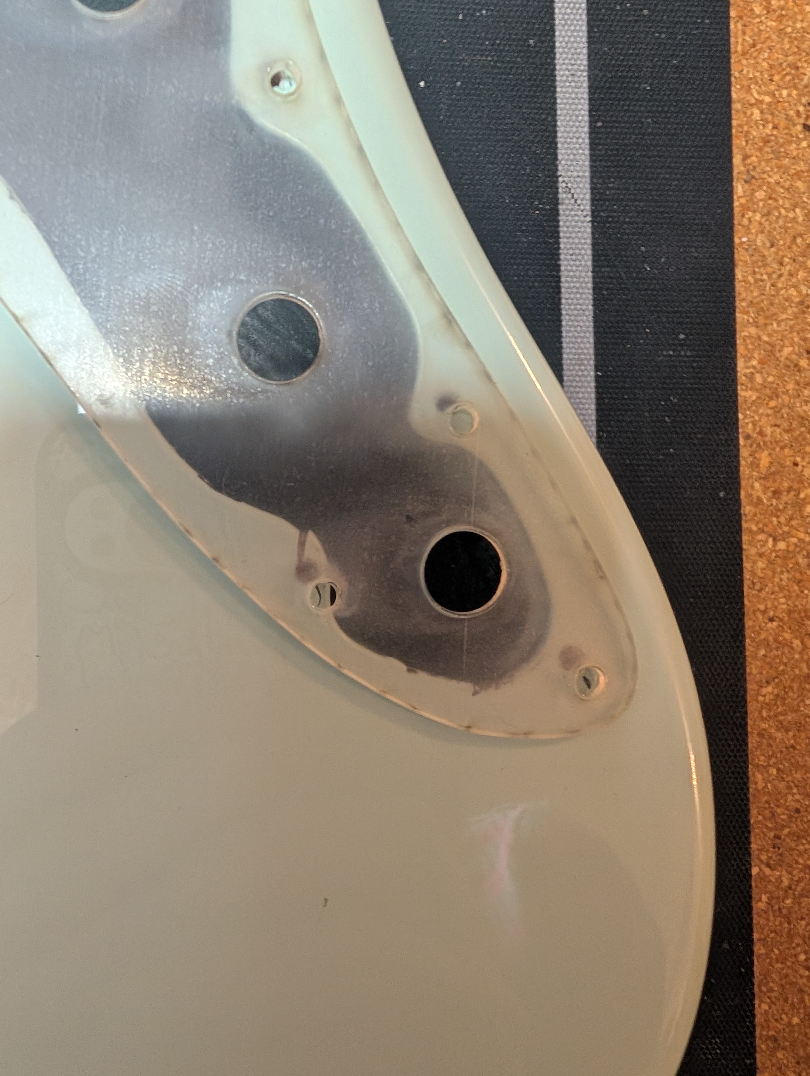
On the first draft, the scale was a bit off. I’m not sure exactly where this came from, possibly the scanner. But I measured the distance between the farthest screws on the original pickguard vs the new one and scaled by the ratio.
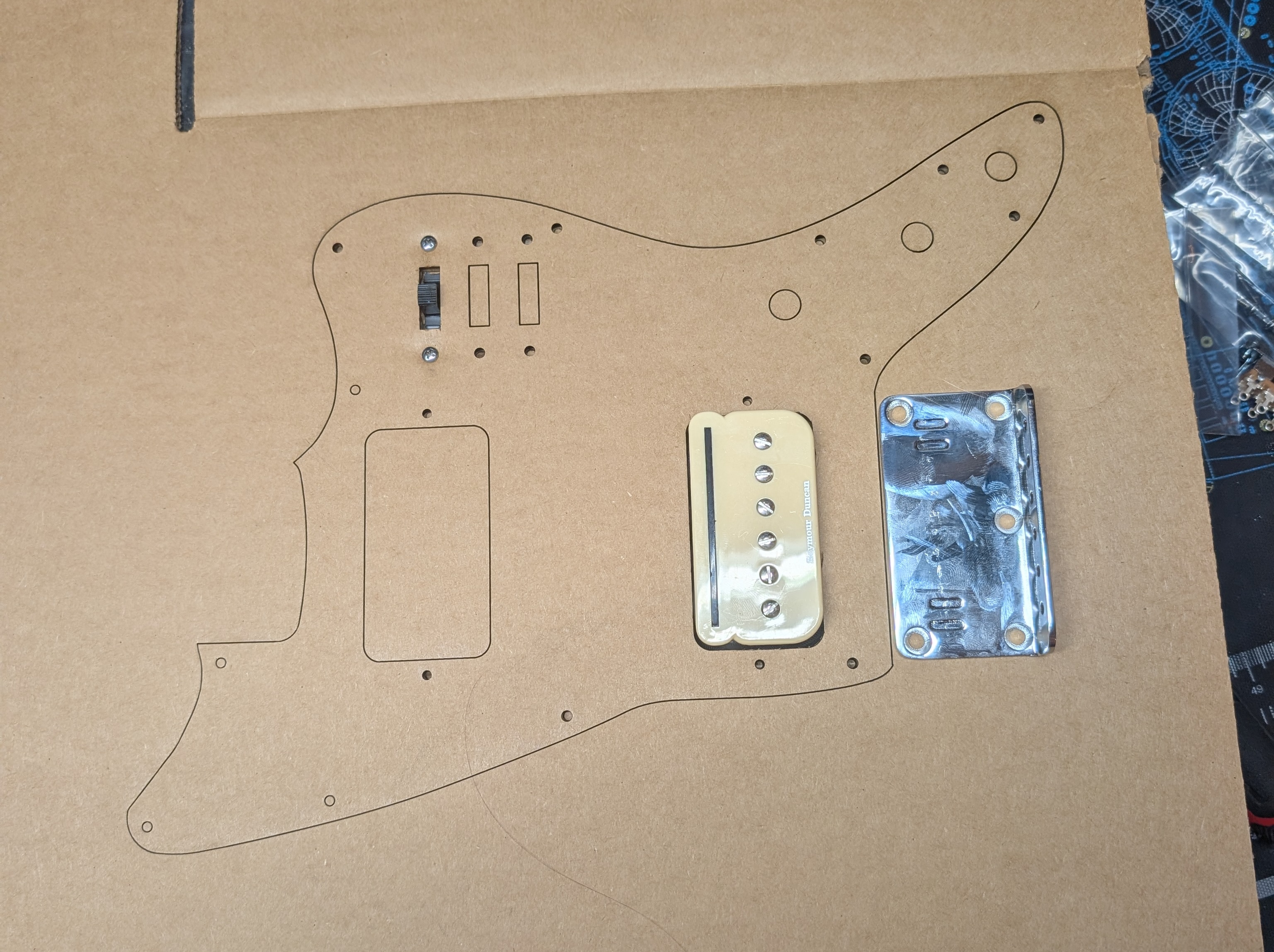
To save material, I printed on cardboard first to check the dimensions. This went really well. The Glowforge cardboard settings didn’t quite cut the whole way through which was nice because I could choose which pieces to cut out the rest of the way. The cardboard is strong enough to hold parts in place for a little bit to ensure everything works in 3d space, and is easy to mark adjustments on.
On my first PET prototype, I tested out the angled router bit I cut to cut the edge bevel. Unfortunately it was impossible to make nice straight cuts by hand, it really requires a CNC to do properly. if I come up with another solution I’ll try it but in the meantime I may just have hard edges.
Bridge
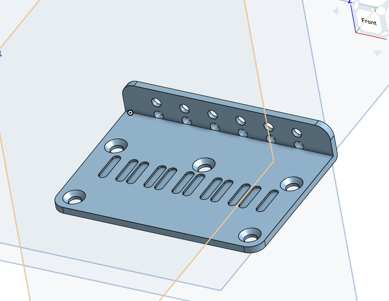
The scale length on the Squier is less than standard, so to account for the longer neck, the bridge needs to move back around half an inch from it’s original position. I could just move it back and re-drill the mounting holes, and I may still do that. But I had the idea to make a custom bridge plate that uses the original hole positions but slides the backplate further back. Once I have a custom part I can use an online manufacturing site to fabricate a metal one. I decided to give this approach a try before drilling any more holes in the body.
I used the online CAD software OnShape to design a bridge. I like OnShape a lot! It’s free if you’re fine with your designs being public, and it uses a really nice parametric system to handle designs. All drawings are based on a constraint system, which means you can go back later and update a constraint and all subsequent design steps will update appropriately. It takes some getting used to at first but once you’ve got a feel for it it’s hard to imagine doing it any other way.
I started by replicating the original bridge exactly to verify my dimensions before extending the backplate. A 3D printed part would certainly not survive the string tension but I can at least verify the dimensions, and the print only takes a couple hours (not quite as fast prototyping as the laser cutter but still quite reasonable). Getting the exact hole distance is a bit tricky because my measurement techniques are not great.
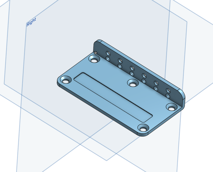
On the second iteration I brought the backplate back, using a global variable that I can update on the fly to adjust the additional distance. I also added trenches for the saddle screws so that they could sit the action quite low without having the screws come out the top and stab your hand when palm muting. I’ll still need one more design iteration to fix some mistakes before I run a version in metal (probably zinc? I don’t know much about metal materials). You can see the part design here.
Body
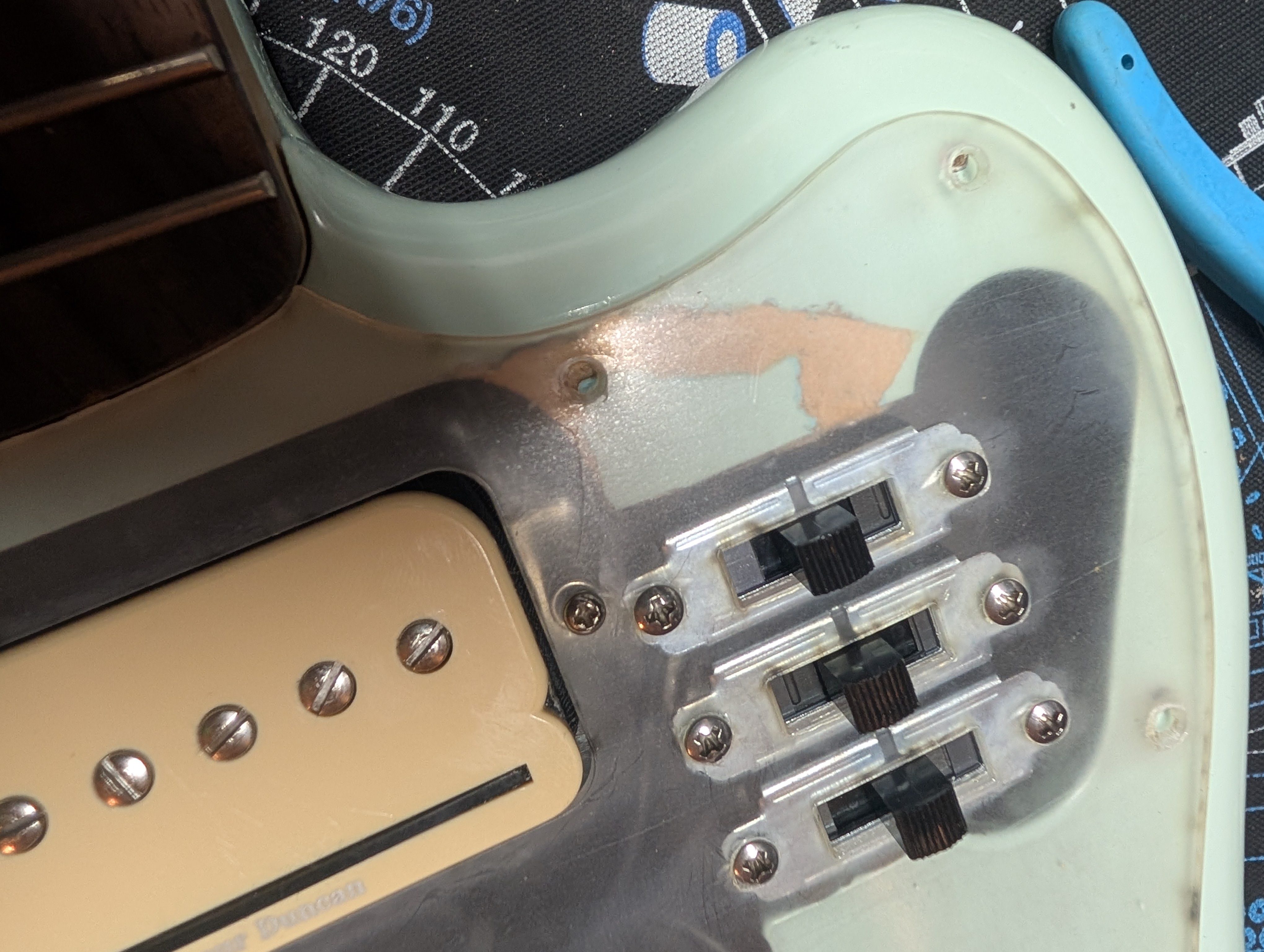
Fortunately not a whole lot of body work is required, but what is is a little terrifying. To support the P-Rails, I want three 3-way slide switches to give full optionality of the pickup wiring (more on this later).
Theres’ quite a lot of room already in the body cavity, but these big Switchcraft slide switches (the same kind used on Mustangs) will definitely not fit where the toggle switch was. I needed to route out a bit of the body to make room for them.
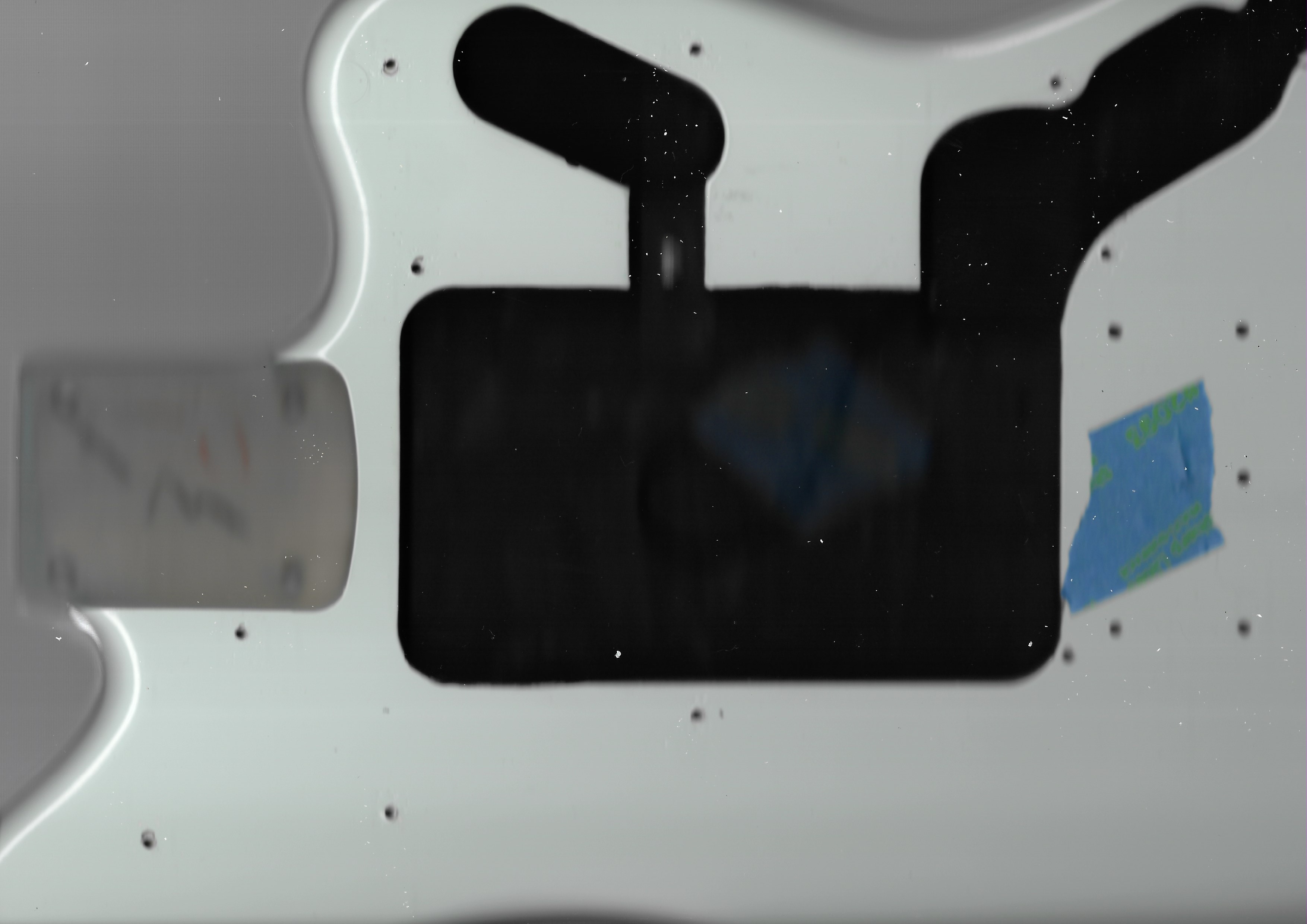
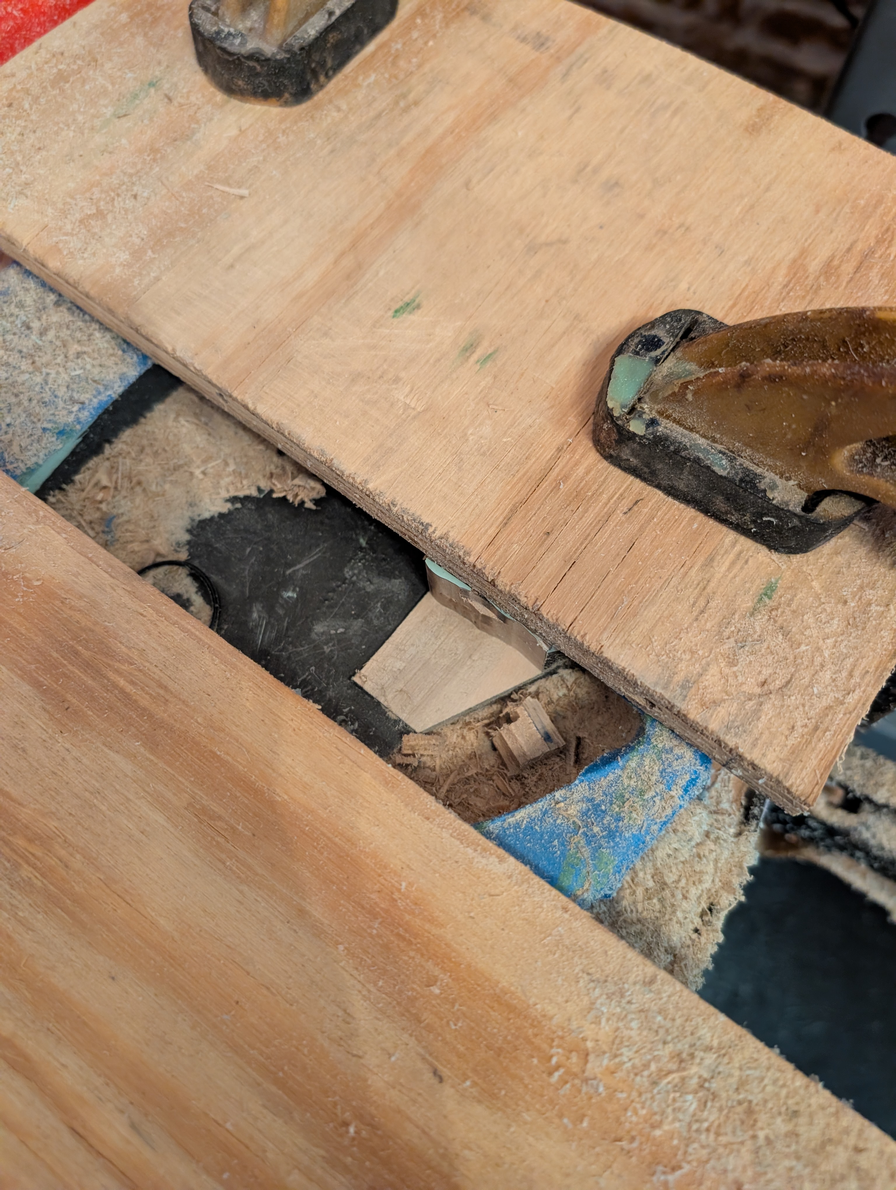
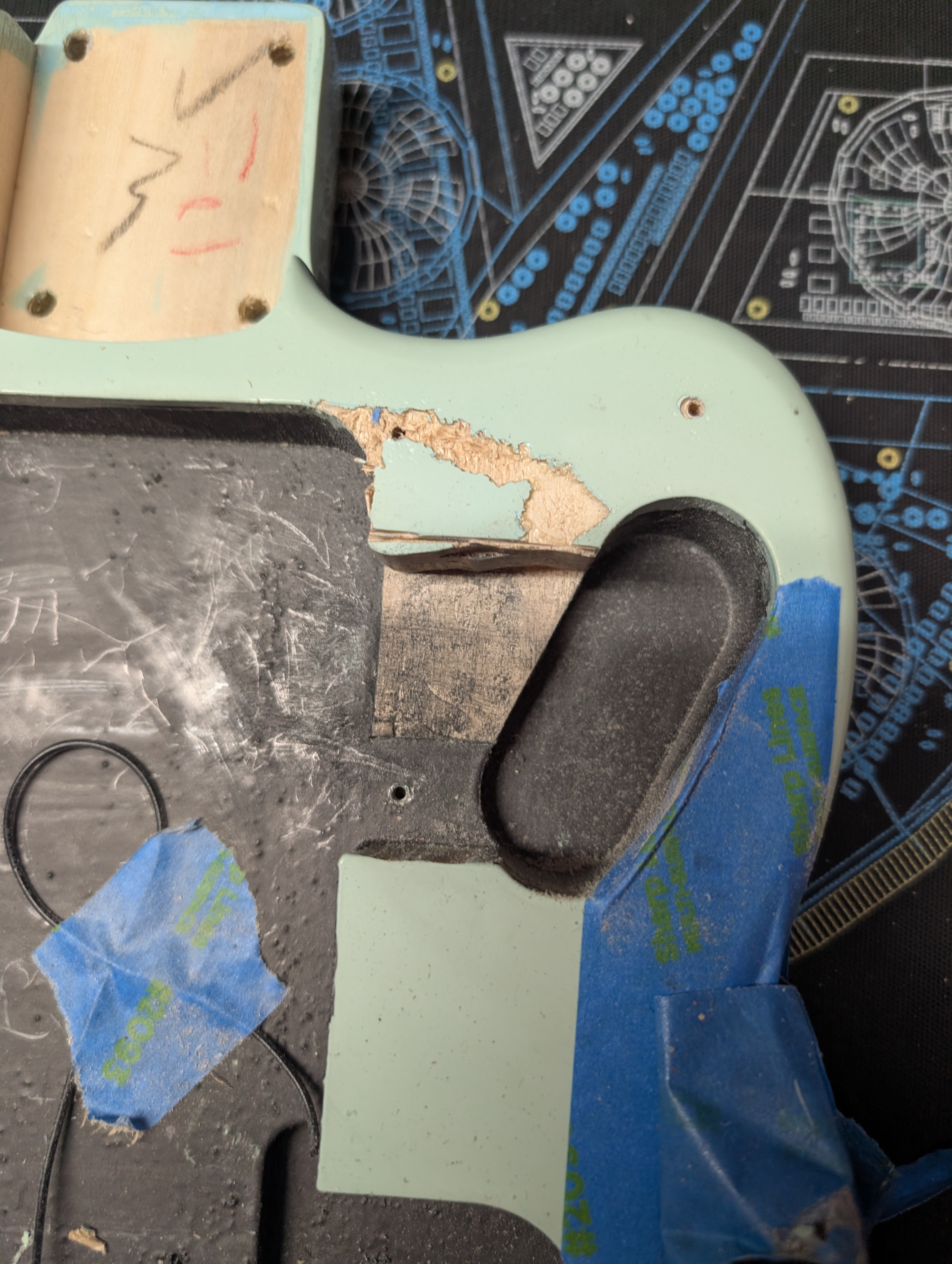
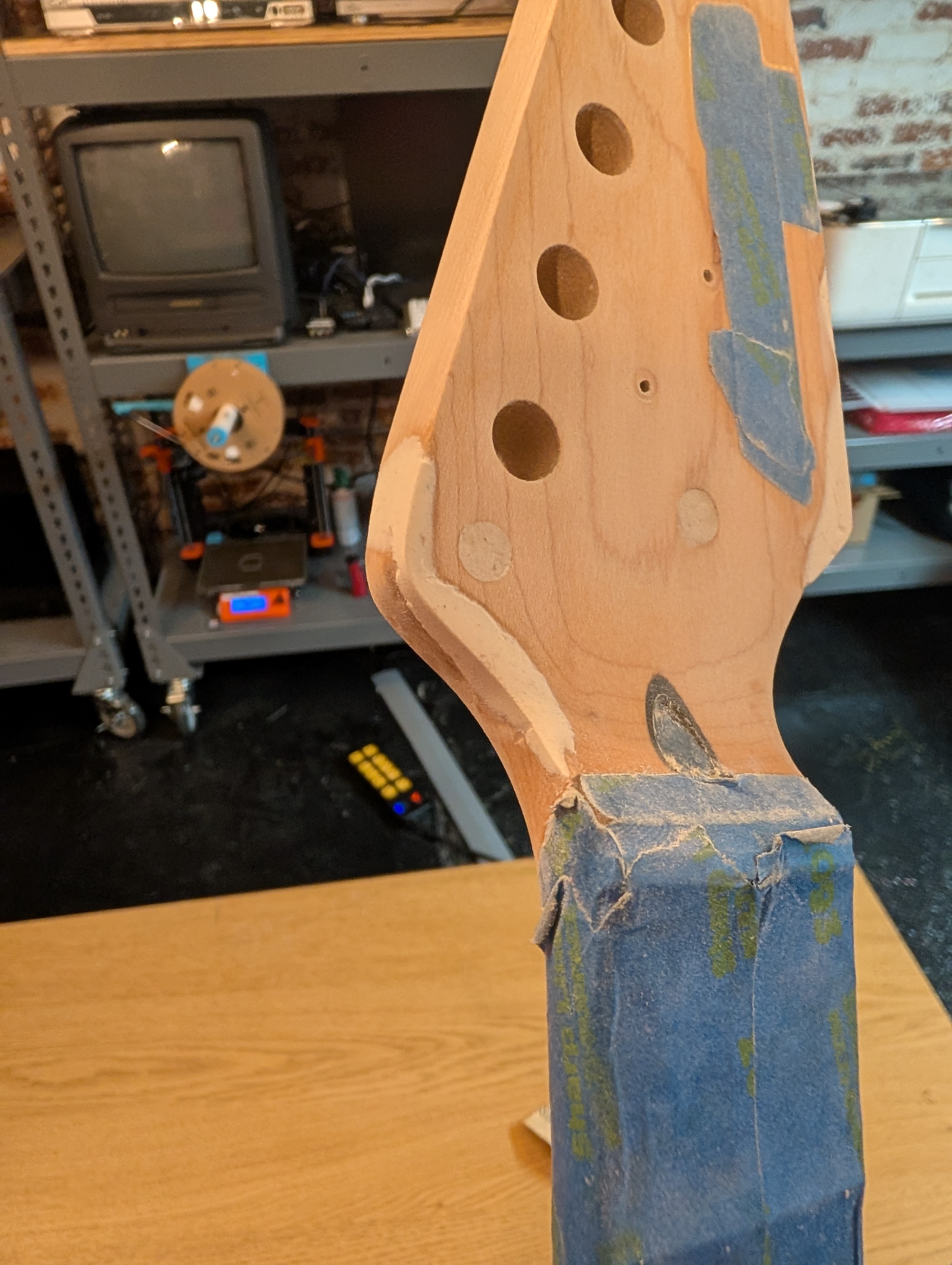
My brother had done some wood routing before and warned me about being hard to control, having a tendency to jump particularly on really hard woods. I covered the body in tape to protect it from scratches, took a deep breath and carefuly started cutting. The first cut went smoothly, giving me a false sense of security. The second cut did not. The router hopped up and bounced across the body, tearing through the tape and the finish.
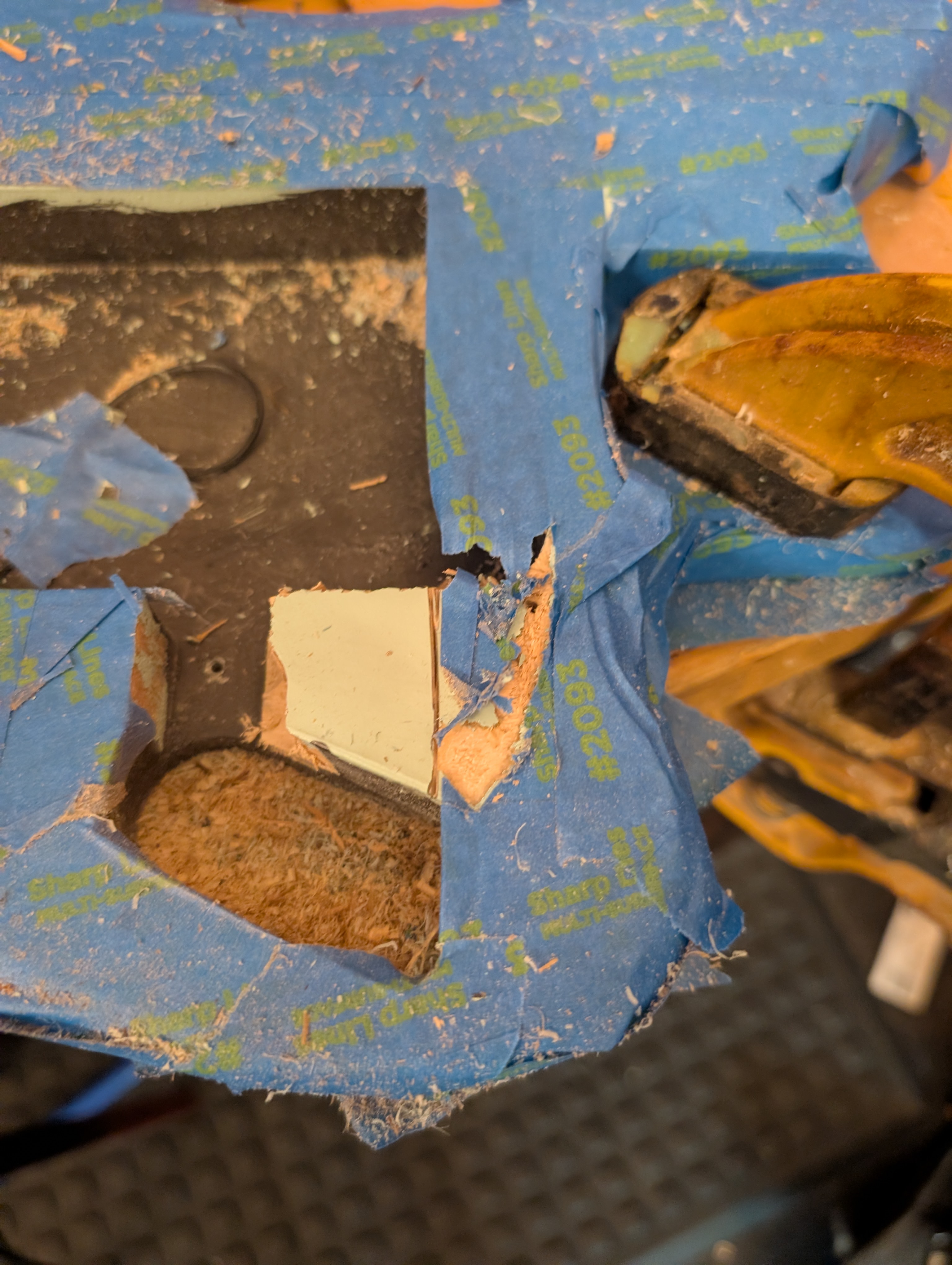
Disheartened but out of options, I had to keep going. I sandwiched the body between two pieces of scrap plywood to try and protect it, and this also had the effect of adding some stability. I took my time and was able to get the rest off without another issue.
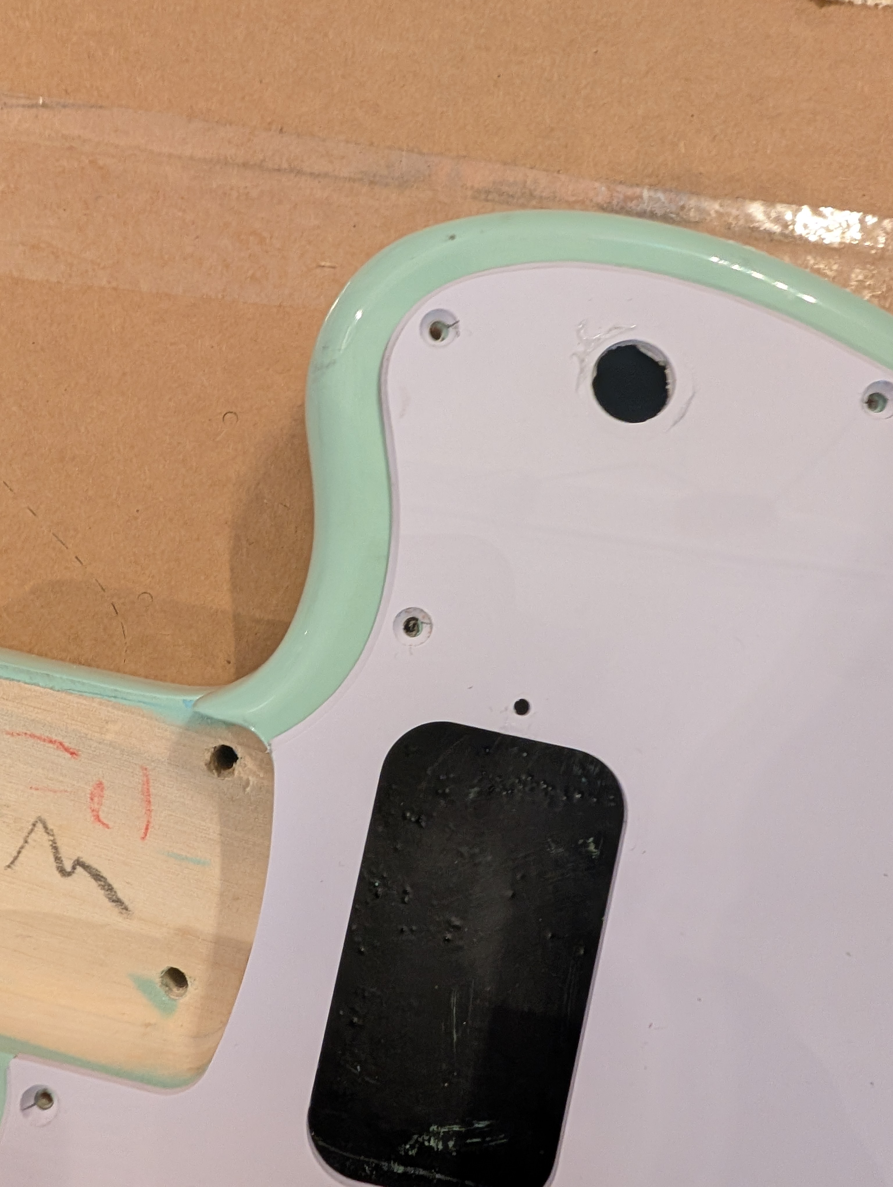
Then I sanded the cuts and assessed the damage. By some huge stroke of luck, the gash was just barely covered by the pickguard! Still not ideal but not completely ruined. I filled the crack with wood filler and made a note to not try routing by hand again. I think I really need a CNC machine for this sort of thing.
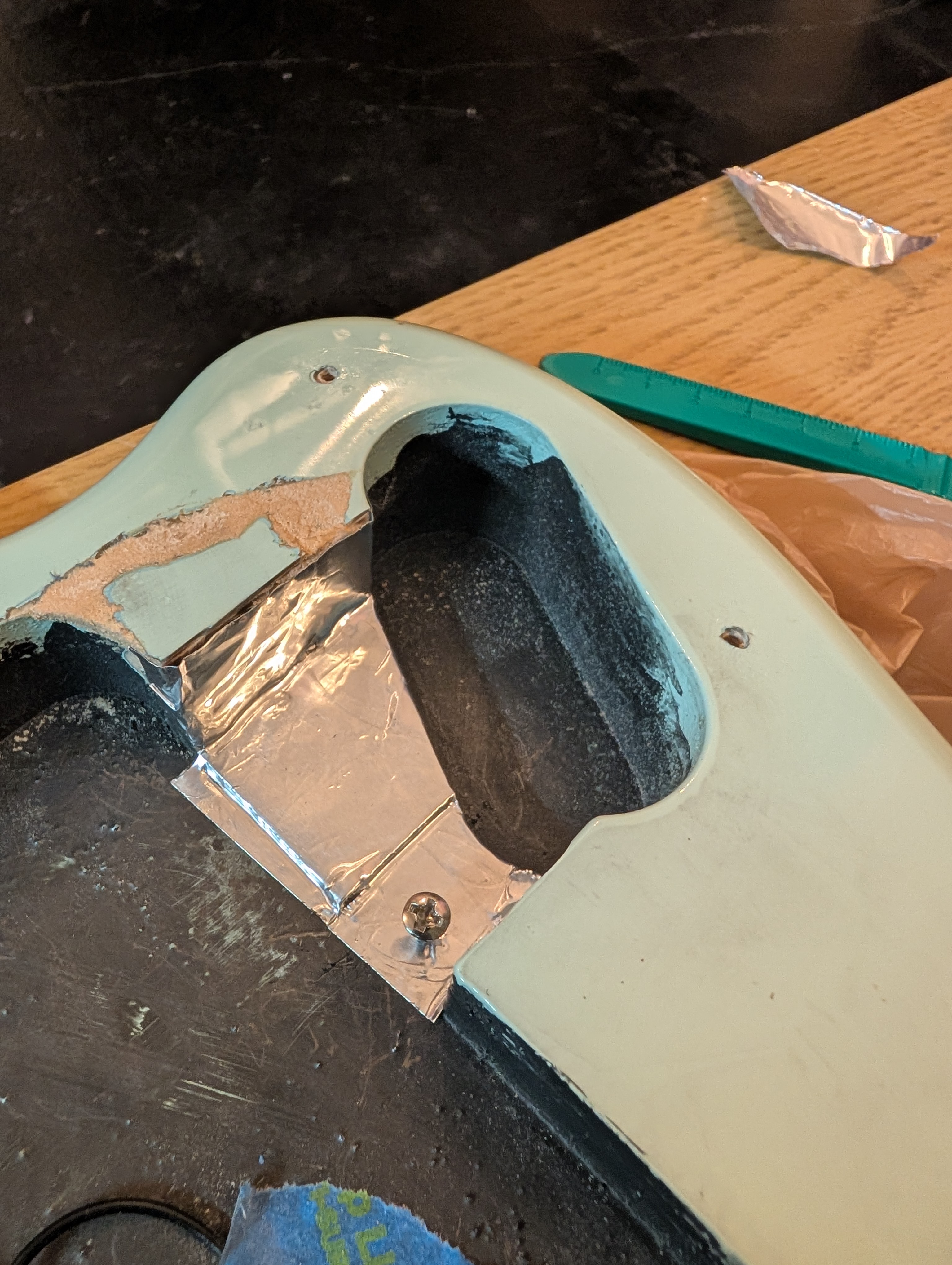
I didn’t have conductive paint, so I used some conductive aluminum tape to cover the routed area, extending to where the grounding screw was so that it would be electrically connected.
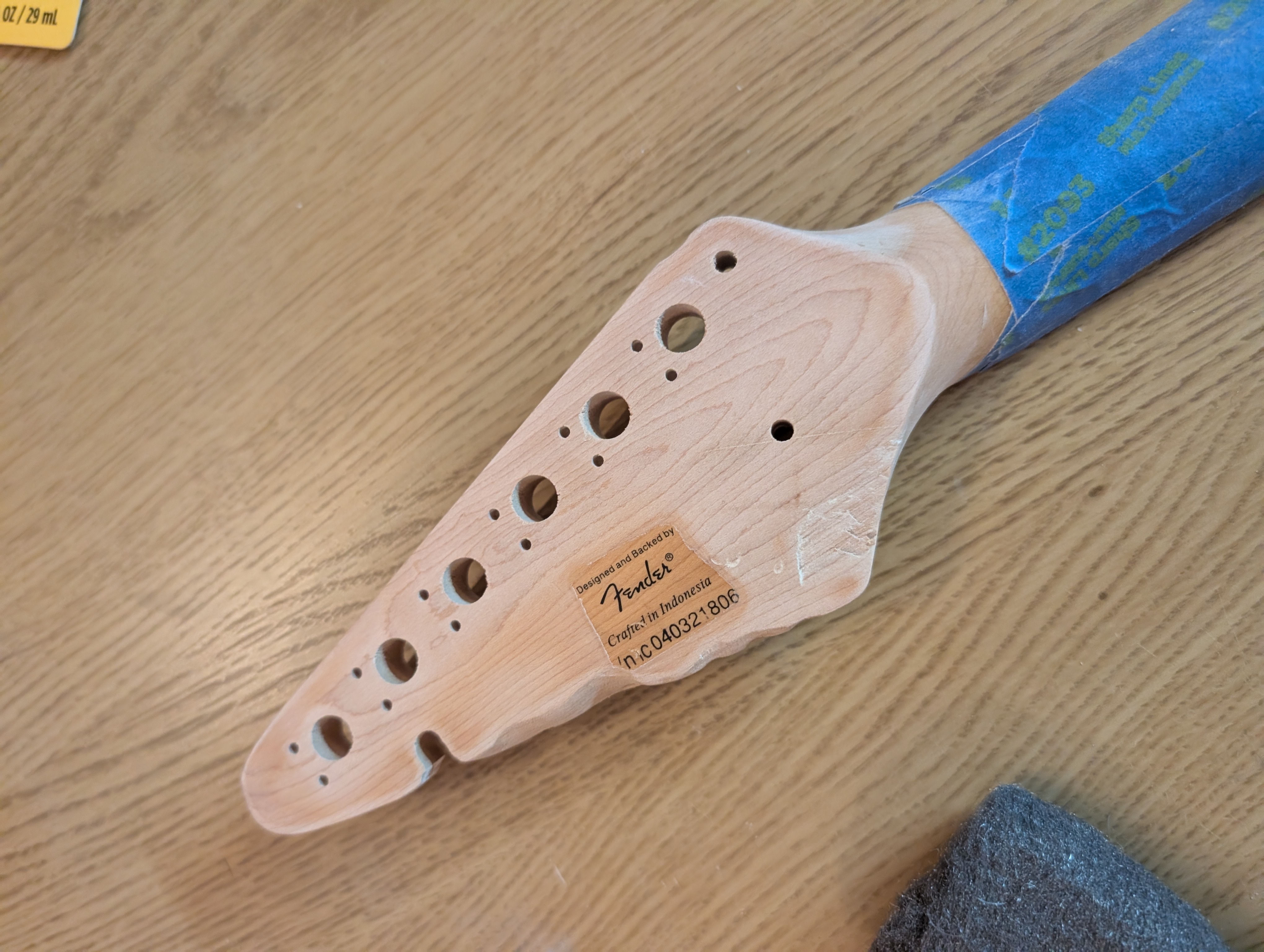
Neck
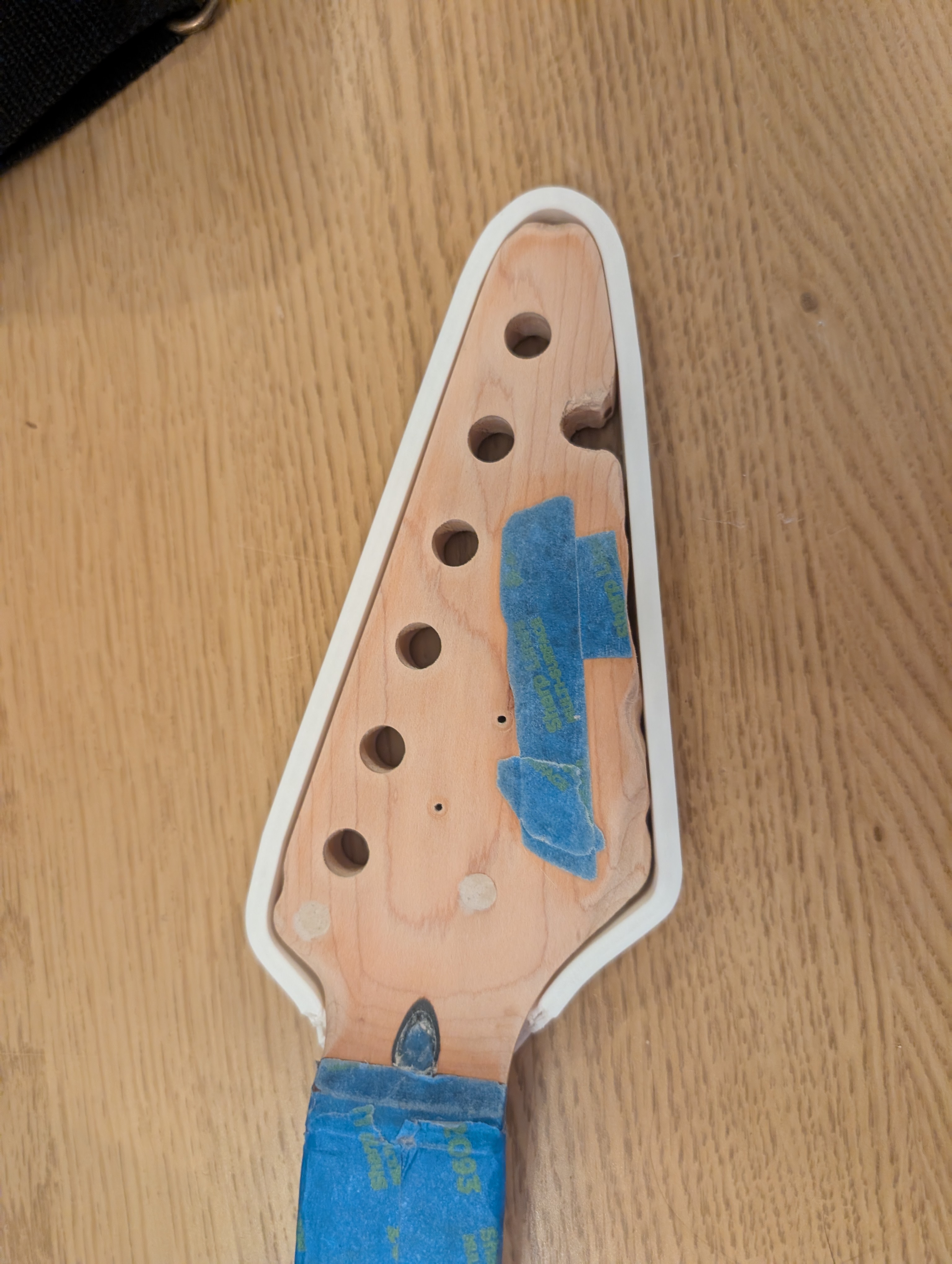
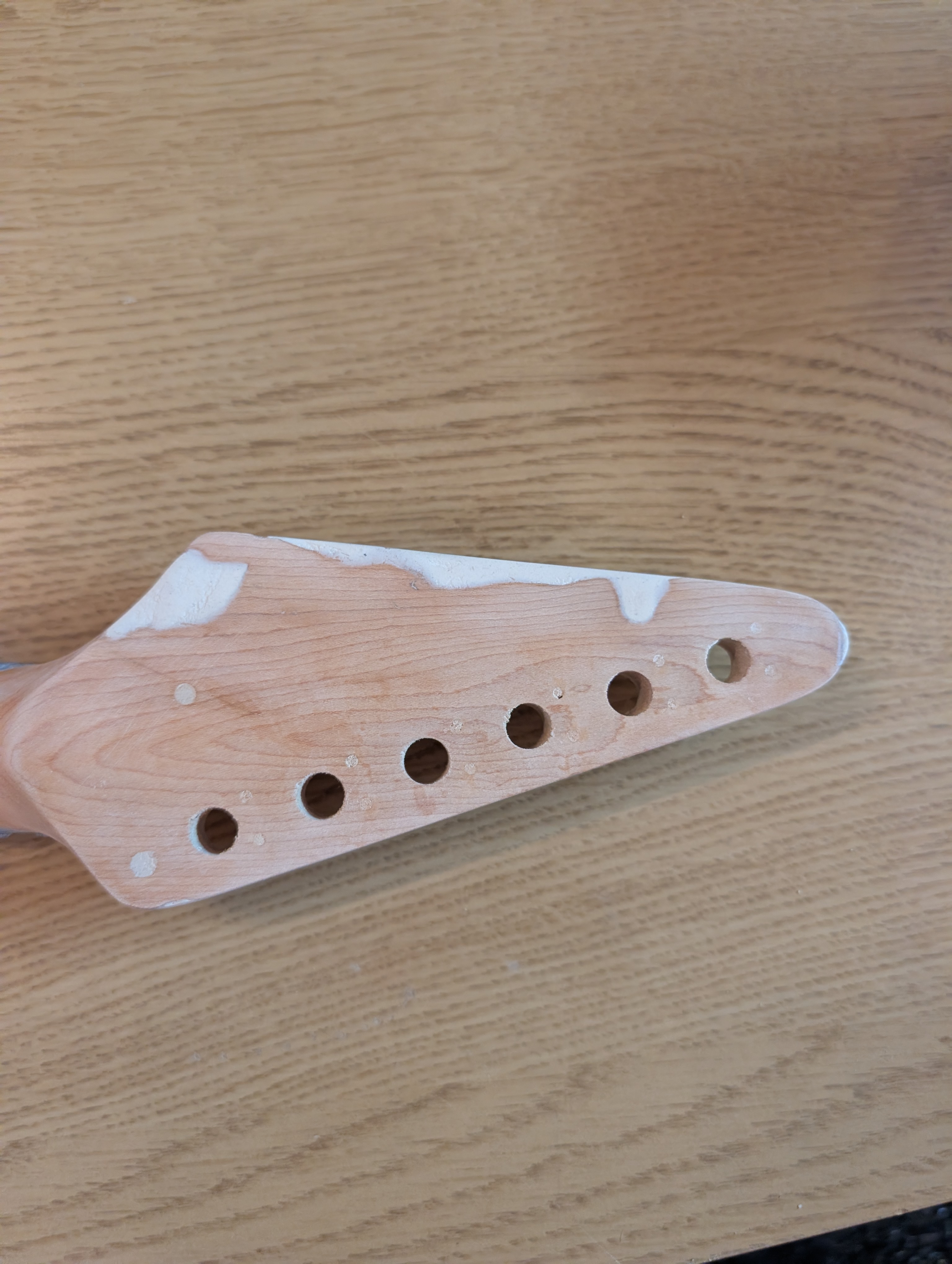
My plan is to restore the shape of the original headstock using wood fillers, and then re-finish it. If it looks reasonably good, I’ll use a clear polyurethane finish like what was originally on there, but if it looks too ugly I’ll give it a solid color finish instead. If possible, I’d like to keep the original “Starcaster” decal but if I can’t that’s okay.
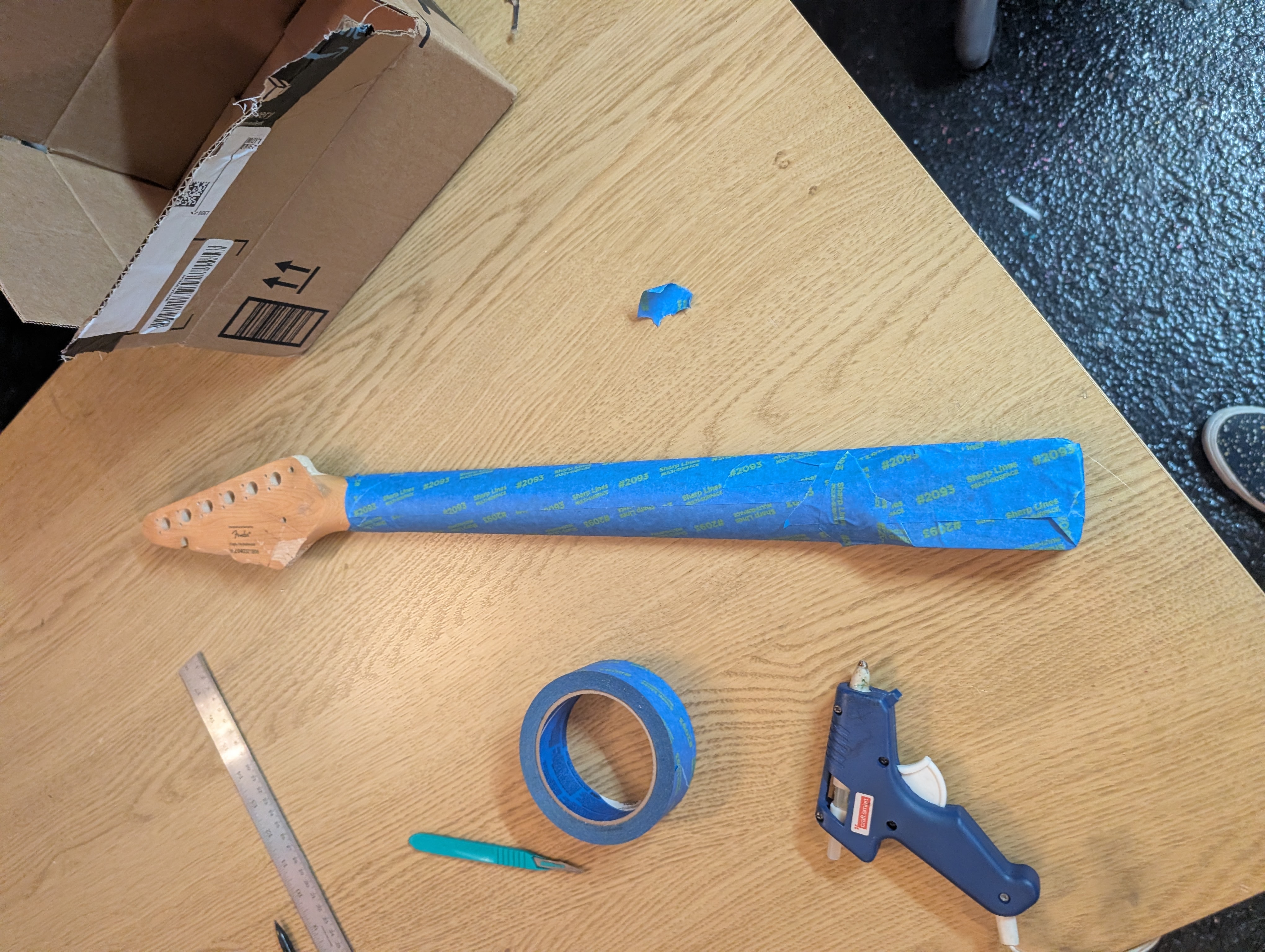
I started by taping off the entire neck except the headstock. To protect the truss rod hole, I filled it with tape, and then used a little hot glue over the top to keep dust and chemicals from getting inside.
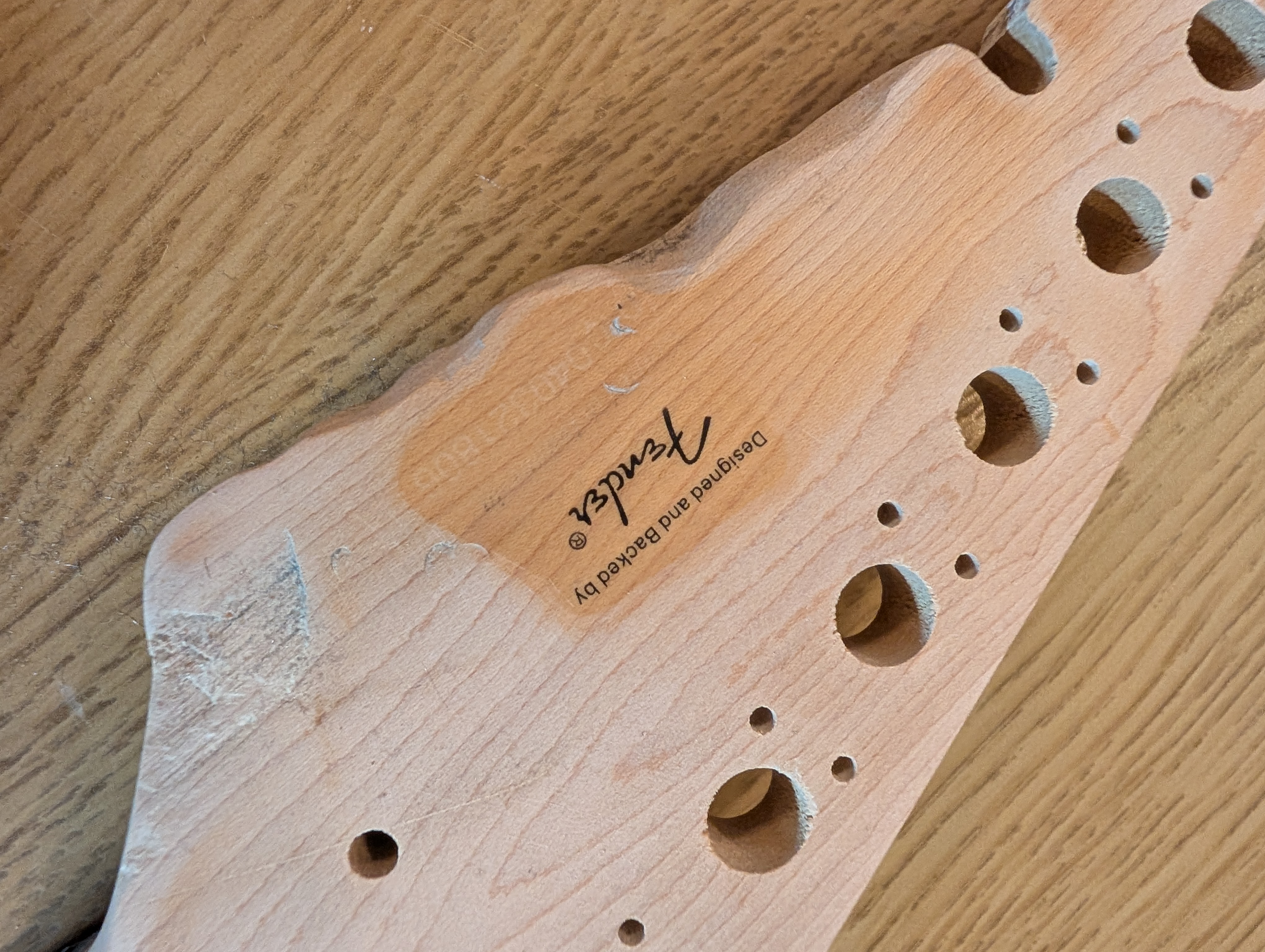
I sanded off the existing finish using 400 grit sandpaper. I also cut and sanded out all the cuts and burns. I saved as much of the sawdust I could, because apparently you can mix sawdust with a little wood glue and paint it on to color match wood fillers.
I had read online that steel wool wouldn’t remove the decals, but I tested on the back and the serial number rubbed right off. I went ahead and removed the rest of the back label. On the front I taped the decal a little closer to the letters and sanded again, hopefully creating a gradient so that any finish color differences are less noticeable.
I found some great advice on wood fillers from this blog post. I got three different kinds:
- LiquidWood/WoodEpox for the biggest areas
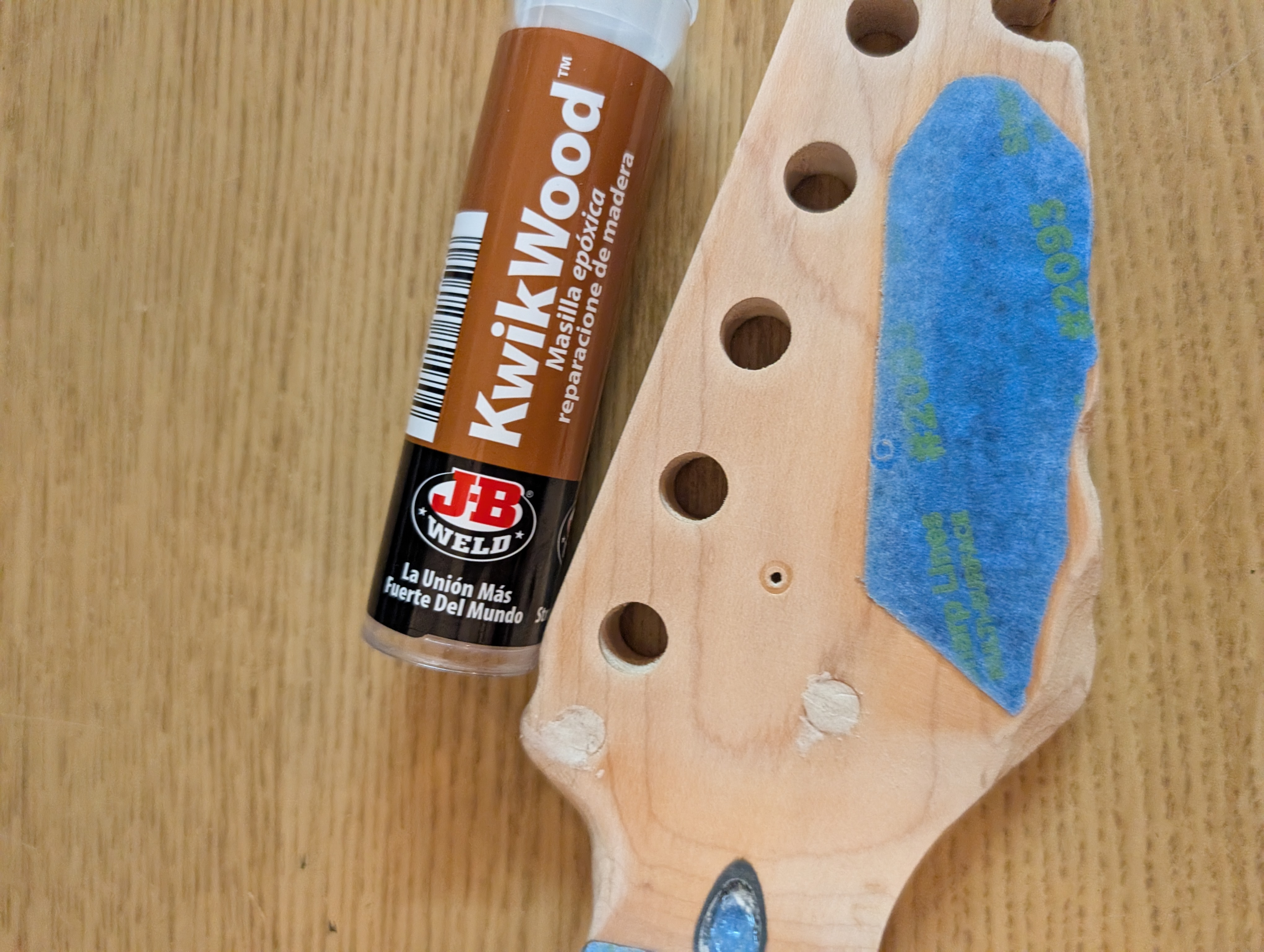
- KwikWood for the drill holes
- Basic Minwood stainable filler filler for the smaller cracks
The KwikWood was very easy to work with and filled the drill holes very nicely. Be sure to use gloves for this as the stuff is toxic.
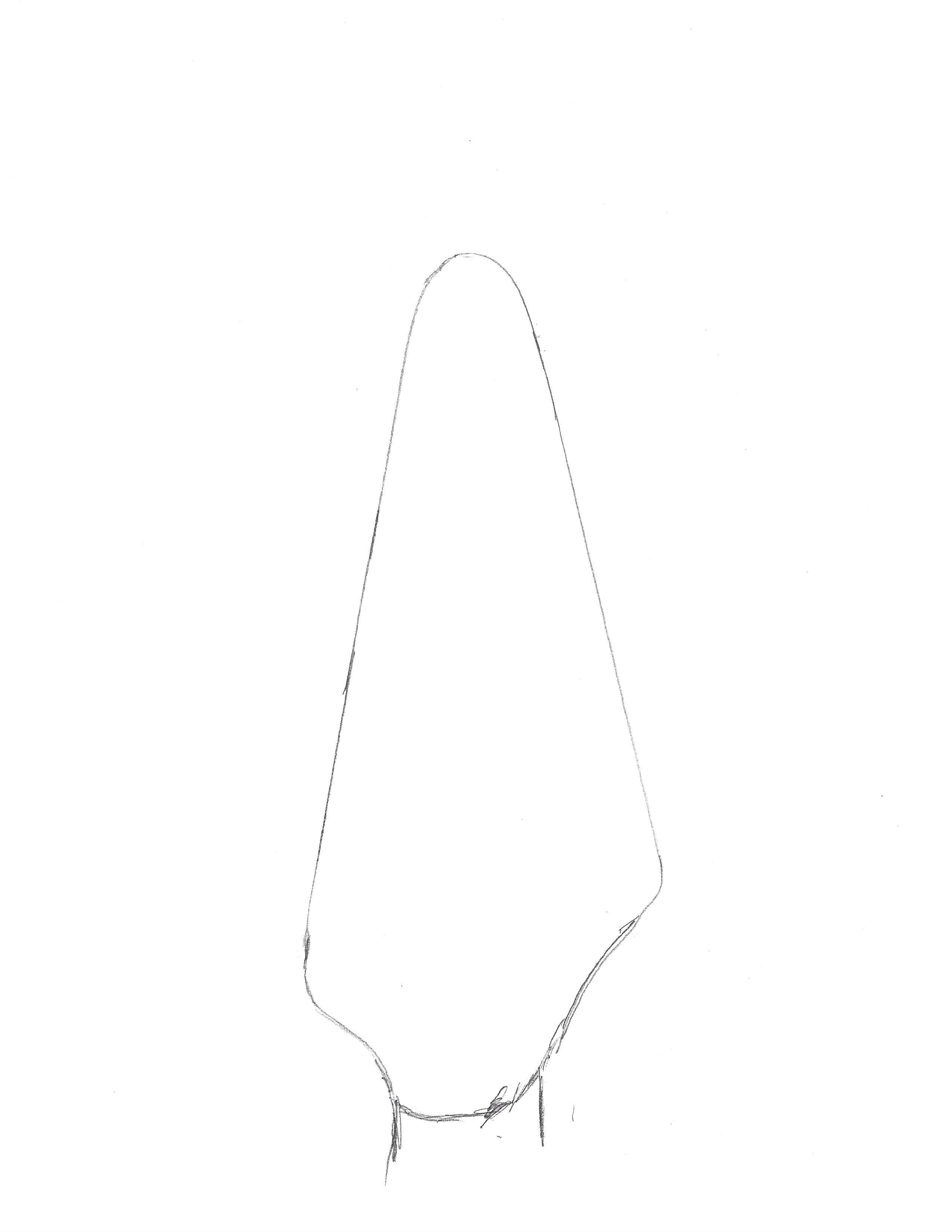
For the bigger fill, I started by making a mold of the headstock. I traced the outline onto a piece of paper, scanned it with the printer, loaded that in to OnShape and did a quick extrusion. I didn’t bother measuring the vertical axis. Instead I just guessed and cut away the excess plastic until it fit nicely.
For the fill I used WoodEpox. This stuff is also very toxic, so use gloves. I’d planned to just use the epox and not the liquid, but it didn’t stick very well so the liquid gave it a nice surface to stick to. Both of these are two-part epoxies; when the two combine it starts a chemical reaction that will harden over a few hours. You’re supposed to use a scraper to apply this stuff, but I found it easier to use my fingers and spread it in place, using the scraper only to flatten stuff out. It’s kind of like a sandy clay; not super easy to work with but not terrible.
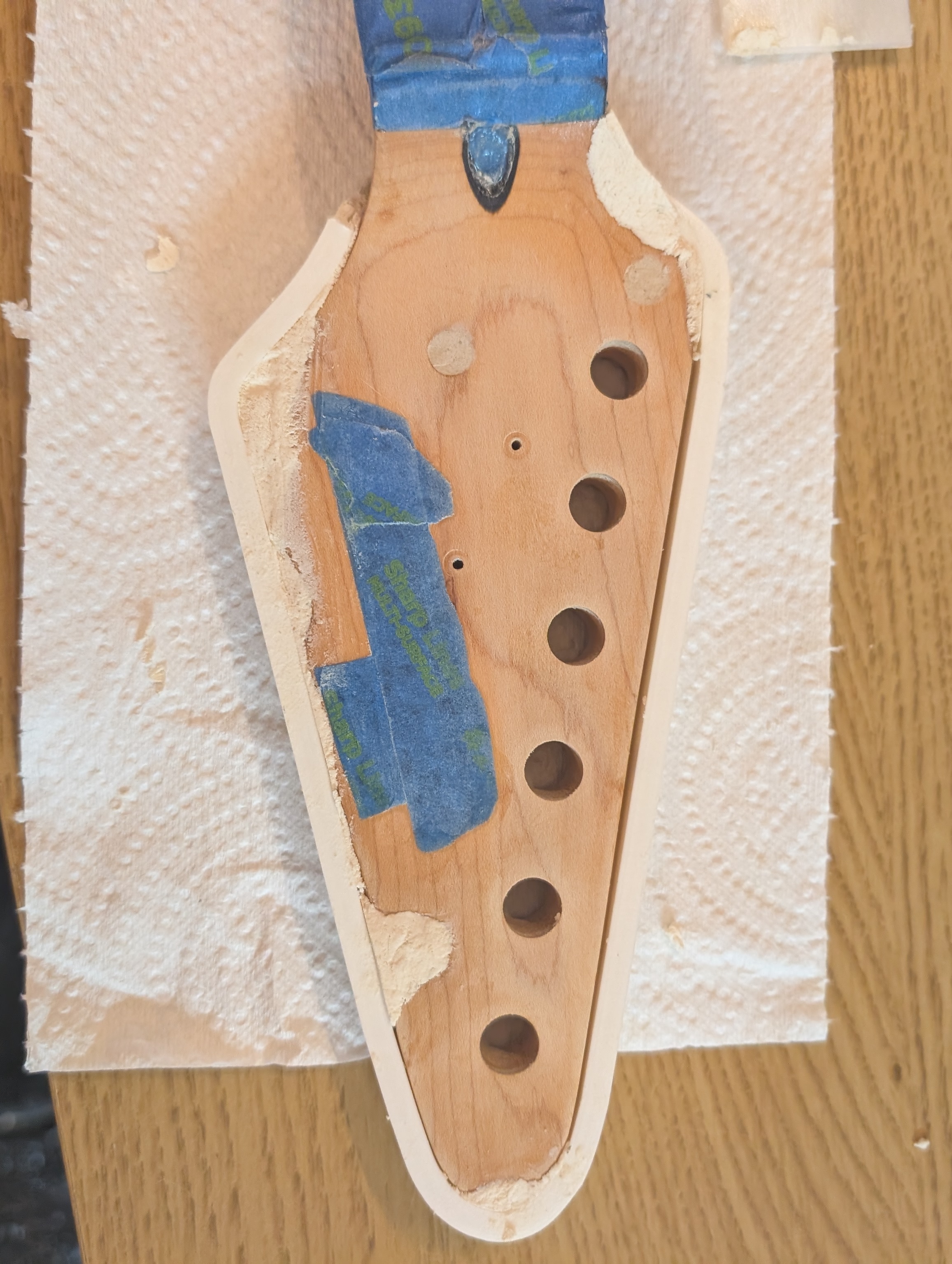
The mold worked excellently. After 24 hours, I was able to sand it down to shape.
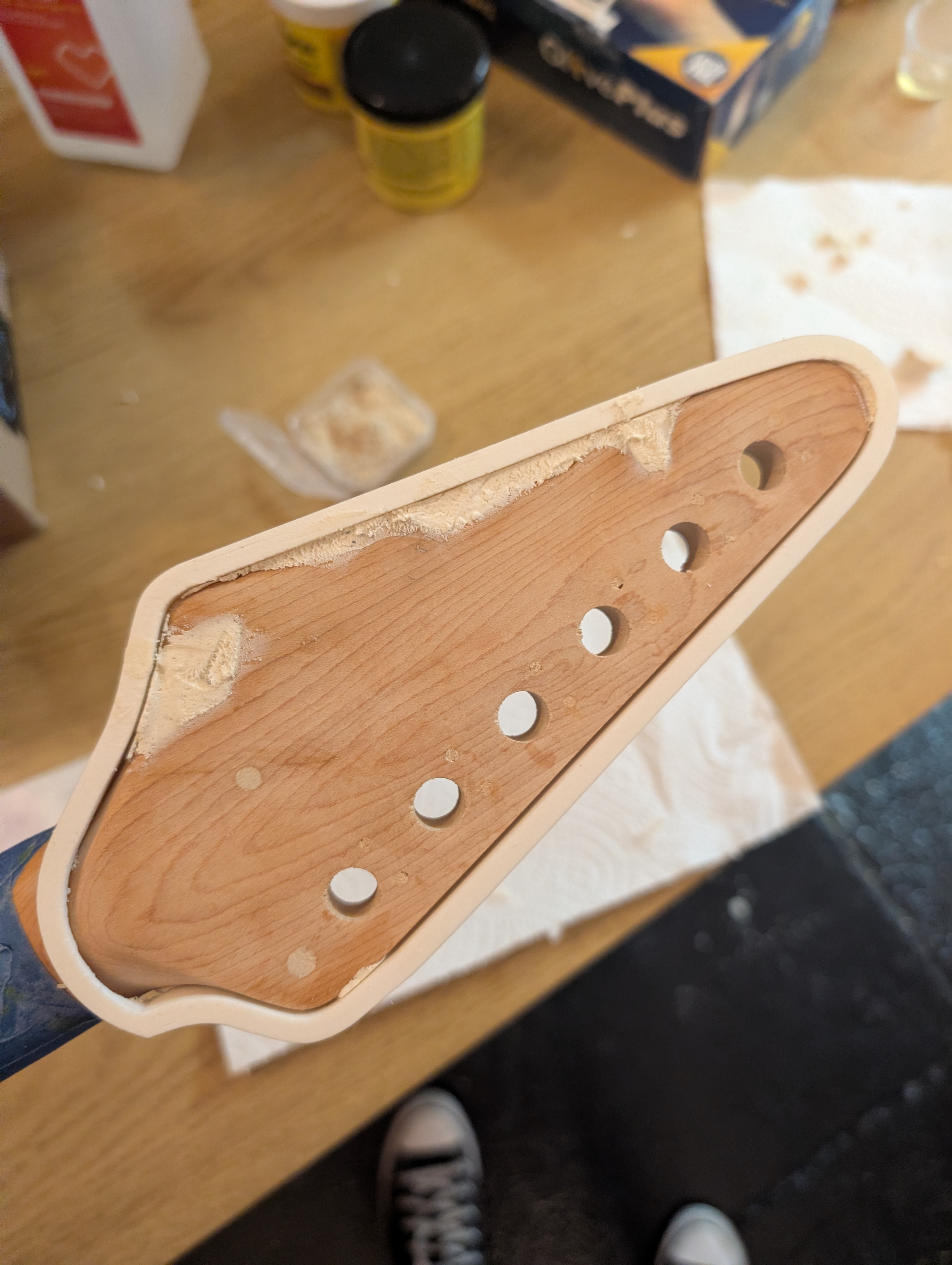
I’m pretty proud of the edge I was able to recreate. I had molded a little extra material, and after a few hours while it was still soft I whittled it into shape, giving it a nice point.
WoodEpoxy dries white. I had the idea to put a layer of basic wood filler on top to give it a more brown color, hopefully making the later sawdust color match step easier. This ended up not being a great idea; the result ended up creating a swirl of two different colors. But overall I’m very happy with how the shape came out. Worst case I can still do a solid color on the headstock.
Tuners
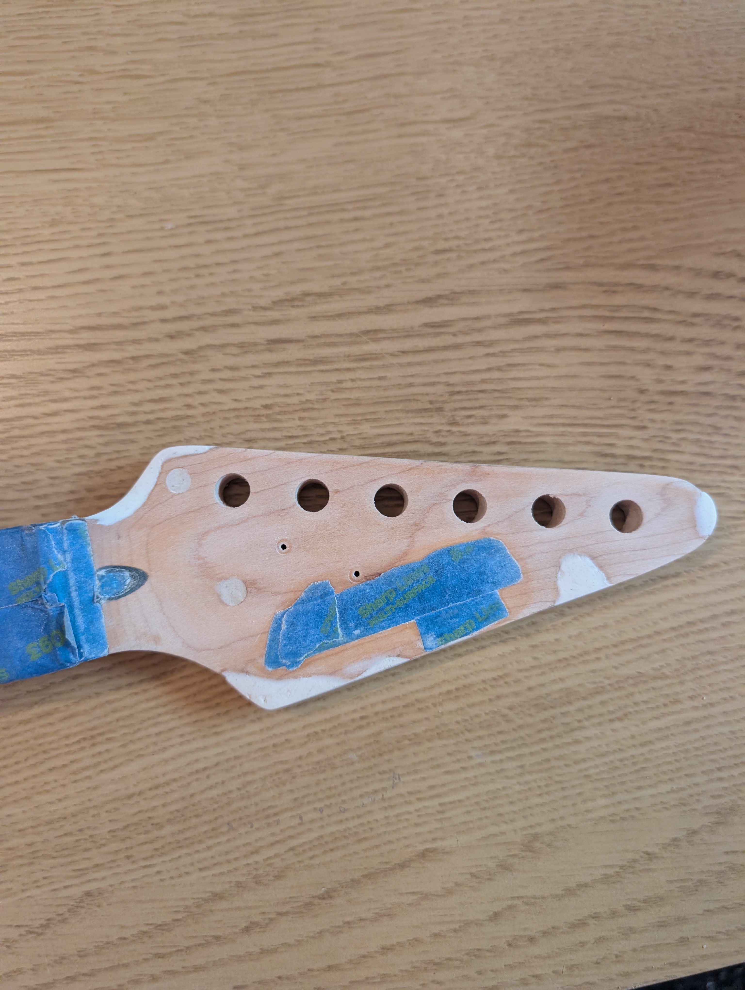
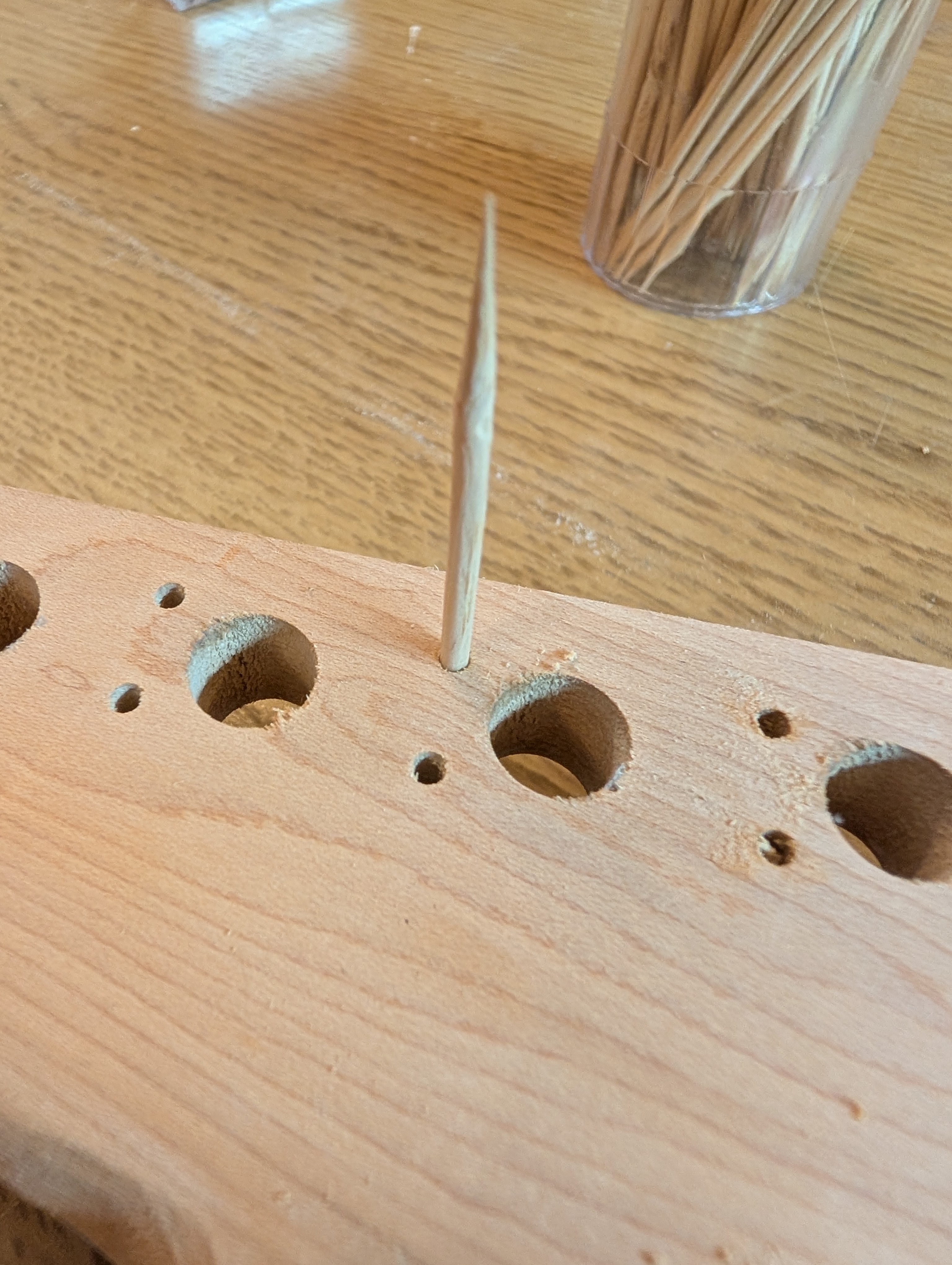
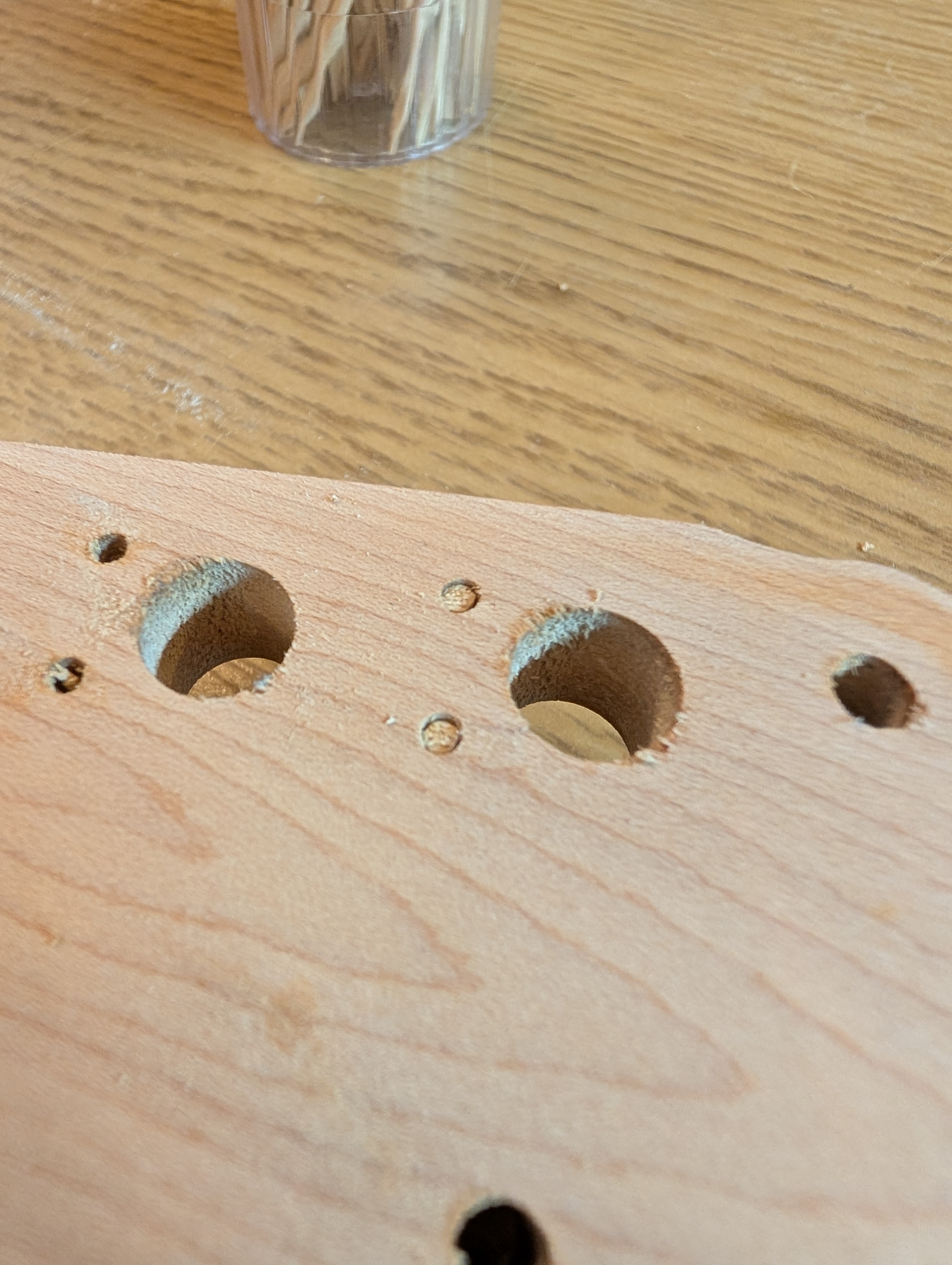
I’m upgrading the tuners from the budget ones to the official Fender ones leftover from my MIM Telecaster when I upgraded to locking tuners. These have guide holes that are a little further out than the original ones.
I filled in the original holes by cutting the point off a toothpick and dipping it in wood glue. I sunk it in the whole to the bottom, then pulled it back up just a little bit and cut it off. That way it was recessed a little and I could use normal wood filler on top. It doesn’t matter too much what these look like since they will be underneath the tuners, but I think they look pretty clean for how easy it was.
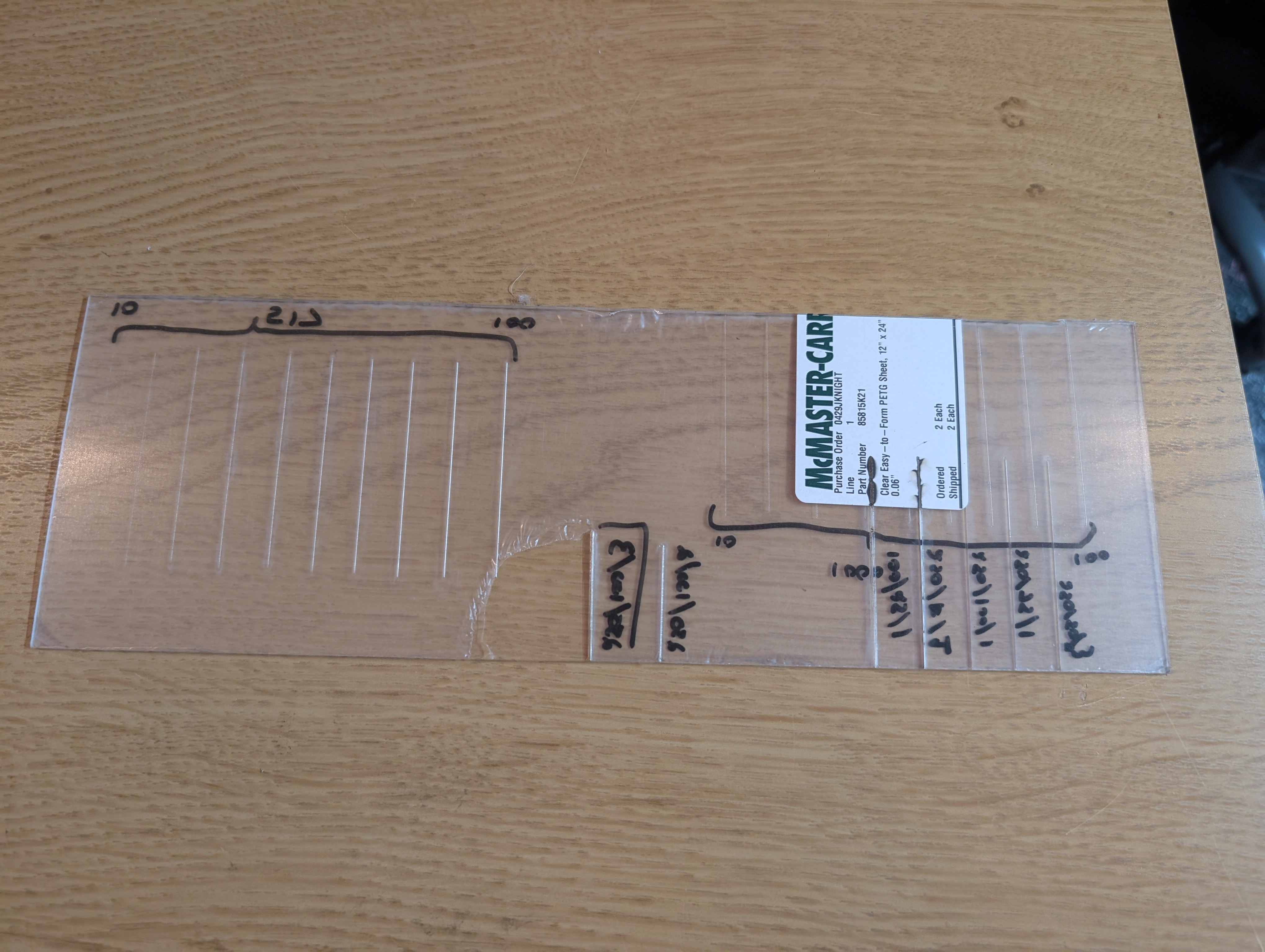
For the new holes, I found a mounting hole guide on Thingiverse. It’s a 3D model but because the laser cutter is so much faster than the 3D printer I extracted the plane dimension and cut it out of leftover acrylic instead. You simply put two tuners in the shim to make sure it’s aligned, then drill the little holes, and repeat.
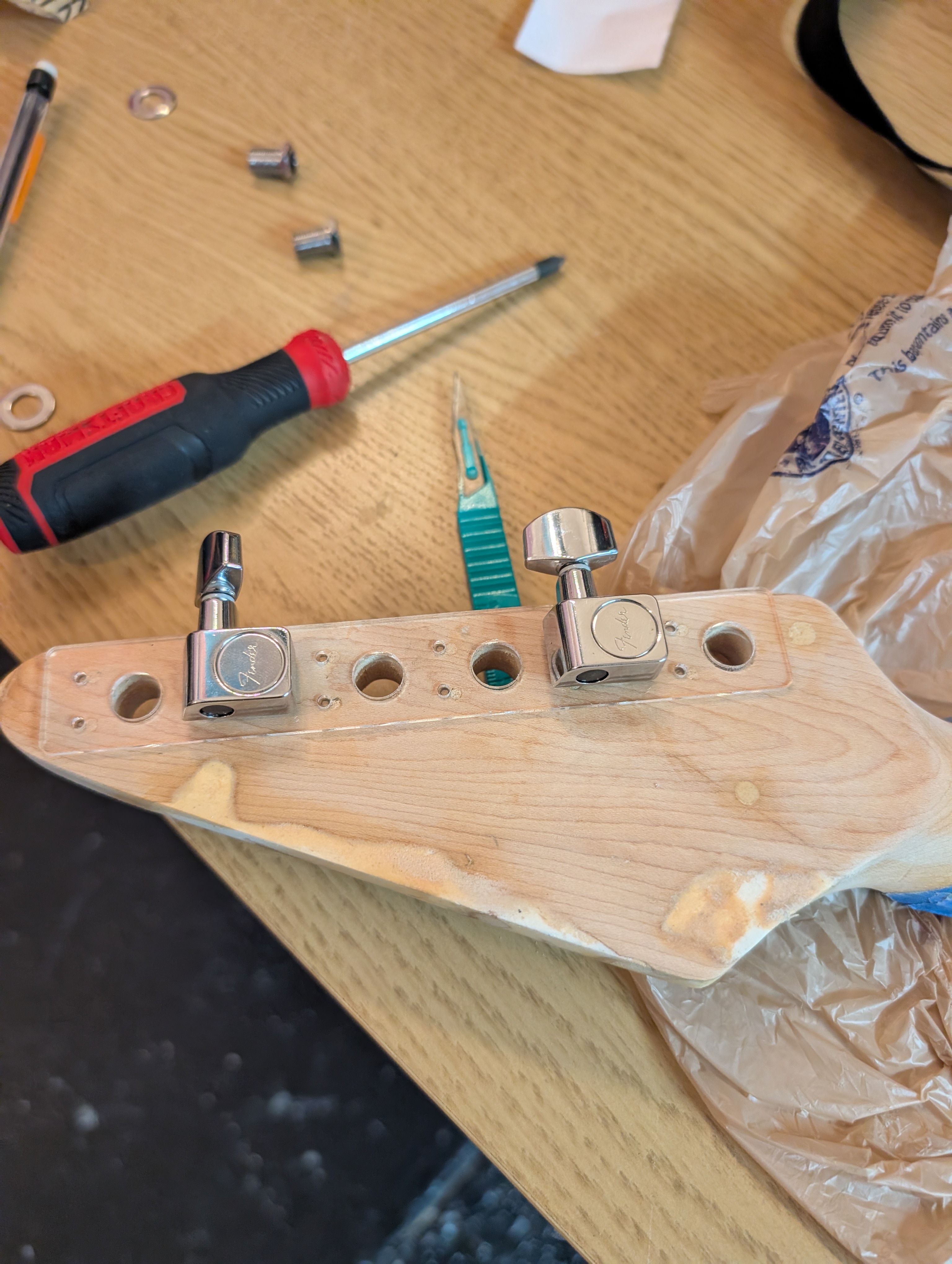
The scale ended up being slightly off, but that meant I had to press them in (giving them a little tap with a rubber mallet), making sure they are nice and snug.
Electronics
My plan for the three 3-way switches:
- Neck pickup selection: Single coil rail / series “humbucker” / P-90
- Bridge pickup selection: Single coil rail / series “humbucker” / P-90
- Pickup select: neck / both / bridge
I’d worked with the P-Rails before, but since they are kinda complicated it didn’t hurt to have a refresher in the form of the official explainer blog post. They are really two separate pickups each, so to get the full functionality involves conditionally shorting out the unwanted pickup. I have “humbucker” in quotes above because alone they aren’t acting has a humbucker, as they are wired with the same polarity in series. Instead, when both neck and bridge pickups are on (in any configuration), their opposite polarities act to reduce hum. How effective this is when they are so far apart I’m not to sure about.
I expected the Switchcraft switches to be 2P3T, that is, each switch has two sets of four connectors, and for each set one connector is alternately connected to the other three. However, these are actually much simpler (mechanically anyway): in the first state, connector 1 is connected to 2, then 2 to 3, then 3 to 4. I was worried this was going to be a problem but it turned out to be pretty easy to work out. It turns out I could have saved some money by getting ON-OFF-ON switches instead (these ON-ON-ON ones were $15 apiece 😬), oh well. I was able to only use one half of each of the pickup mode switches, though I had to use both sides of the pickup selector switch to get it to work.
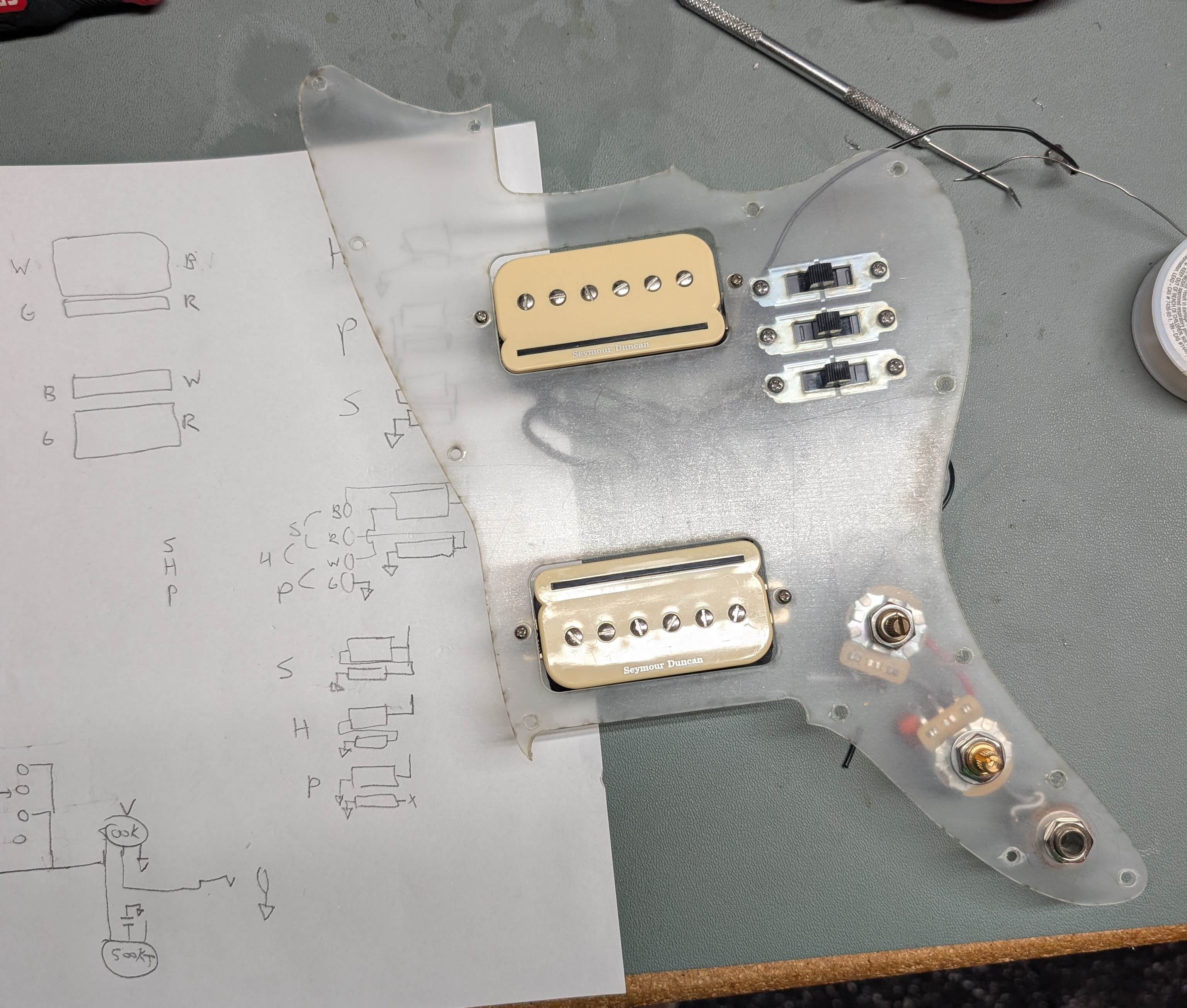
Beyond the switches the rest of the wiring was straightforward, and worked the first time. I reused the jack from the Squier (and also repurposed their nice signal+ground wires) but I upgraded the pots to some nicer ones. It ended up being really convenient to have the pickguard be clear during prototyping so that I could see where the wires would fall.
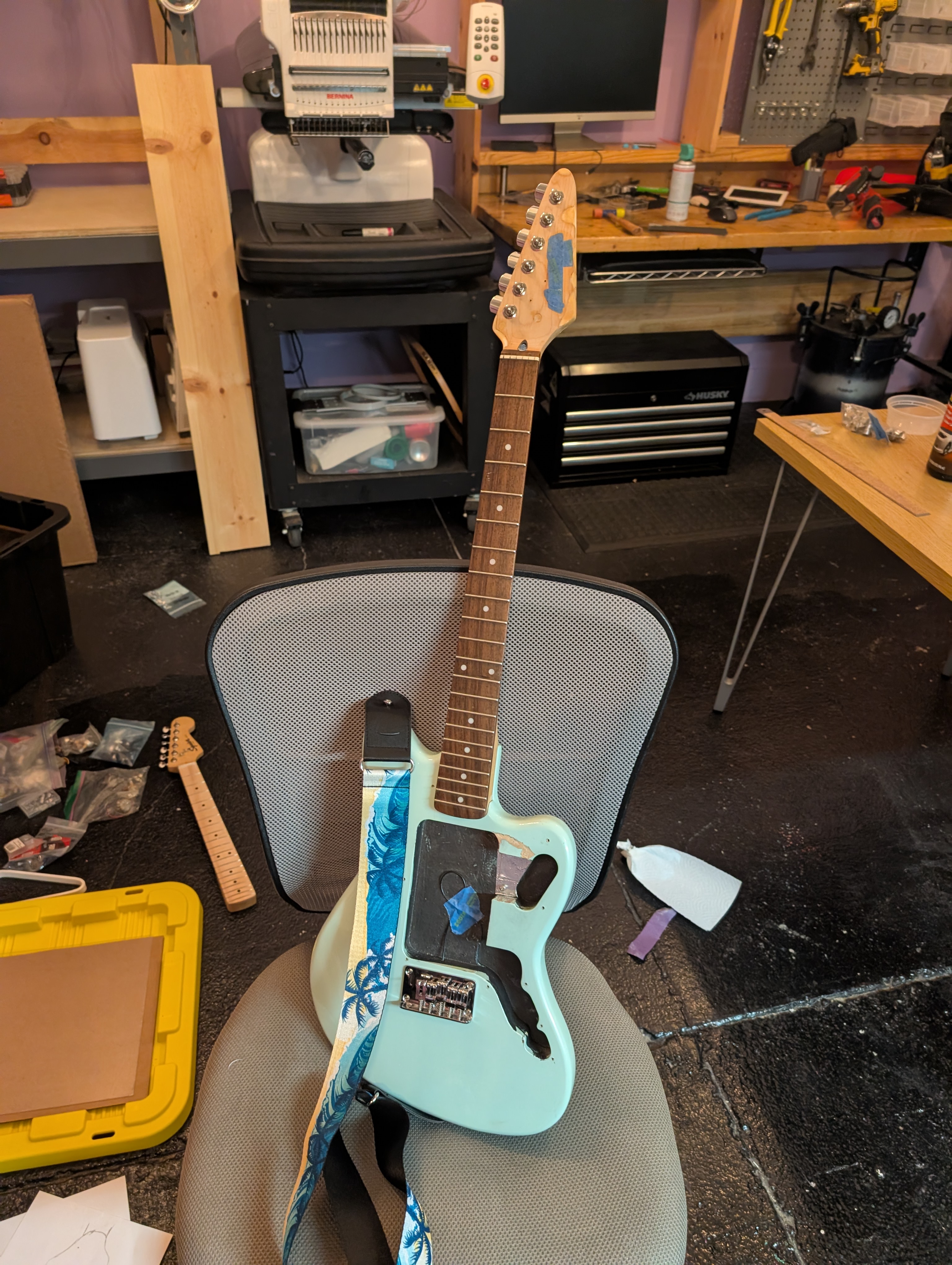
Putting it together
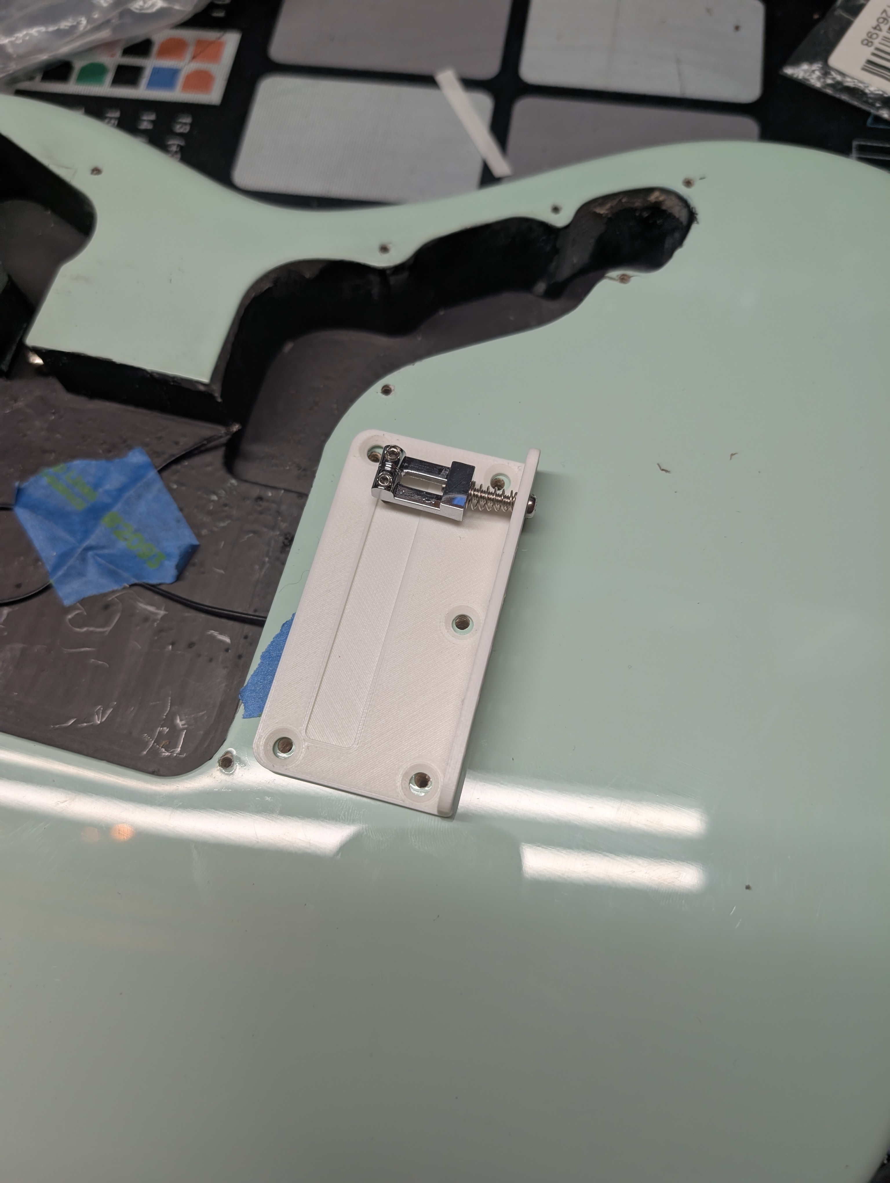
At this point I decided to see where things stood and get ahead of any issues by assembling it in the current state. There’s no way the 3D printed extended bridge would hold that much string tension, so I put the original bridge back on, knowing the intonation would be atrocious.
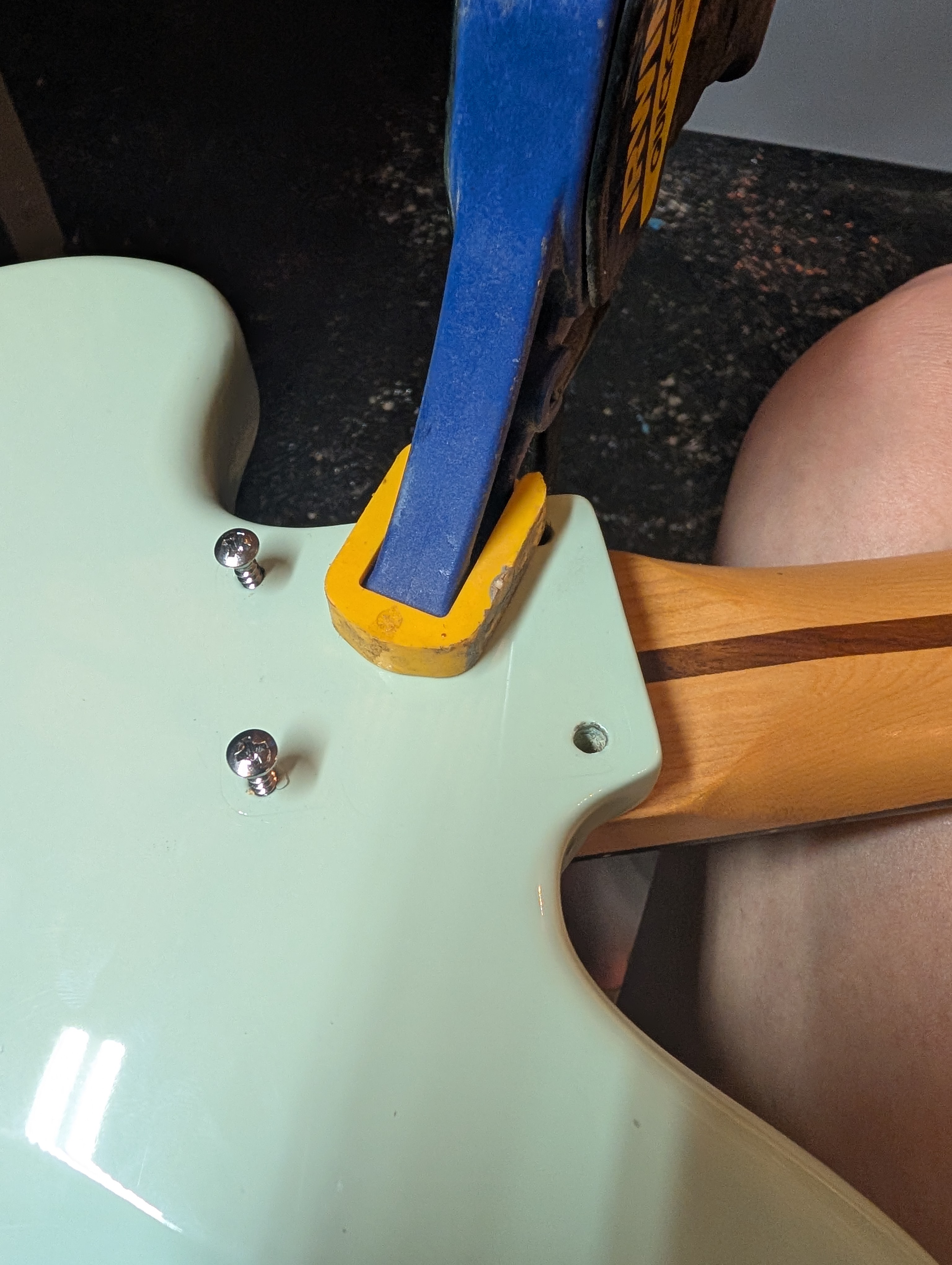
To my dismay, despite the neck pocket being the same size in the two guitars, the mounting holes were not in the same place, and I had to drill new holes into the neck. This was another dangerous task I wasn’t looking forward to. Any misalignment of the neck will make the guitar unplayable, and a mistake in drilling could ruin the neck. But it ended up being okay. I pushed the neck tightly in towards the bridge and held the pressure while at the same time using a clamp to apply the perpendicular pressure into the body. Once I drilled small pilot holes and bolted two of the screws in, I had a reference point to do the other two. I used an electric driver very slowly with a high tension to turn the screws most of the way, and then did the last couple of turns by hand.
I didn’t get a picture of the assembled guitar but it went together nicely, and doesn’t sound half bad. The pickups offer a lot of flexibility in tone, and the neck feels very nice. It holds tune a lot better than the Squier Mini did (although the intonation was atrocious beyond about the 5th fret). The neck is noticeably heavier than the body, but not so much as to effect playing. I didn’t bother to adjust the action since I still have to re-work the bridge.
Next Steps
There’s still more to do, but the results so far are promising, and all the hard parts are behind me. Stay tuned, hopefully next week, for the next (final?) update:
1. Color-match the wood filler and apply a finish
My plan is to use a rub-on polyethylene, which will hopefully match the existing neck finish. If not, or if the sawdust color match doesn’t work, I may look into buying some mint green paint instead.
2. Finalize design of the bridge and get it fabricated
In addition to the adjustments I have to make, have an idea to add a sort of ramp to guide the strings up and into the saddles that I want to test out.
3. Apply graphics to the pickguard
The decal (plus a backup) should be arriving Monday. Hopefully my plan for attaching them works and it looks good through the clear pickup. The pickup screw holes are still not exactly aligned. I was able to flex it into place but I don’t know how that will affect the decal. If I have to run another pickguard I’ll certainly fix it.
4. Setup
Adjust the action and intonation, level the frets and adjust the truss rod. The fret leveling makes me a little nervous but hopefully everything goes smoothly. I have a nice 6 inch fret file I got from StewMac (everything of theirs is so expensive!?) and a lot of masking tape, hopefully that’s all I need.